2-8 Voltage and Temperature Measurements
Controlling autozeroing modes
For front panel operation, the two autozeroing modes are controlled from the SHIFT >
CONFIG menu as follows:
NOTE For remote programming, the commands to control the two autozeroing modes are
listed in Table 2-2.
1. Press SHIFT and then CONFIG to display the present state of Front Autozero; Y = yes
(enabled), N = no (disabled).
2. To change the FRONT AZERO setting, use the or key to display Y or N.
3. If you do not wish to view or change the Autozero setting, jump to step 6. Otherwise,
proceed to the next step.
4. Press the key to display the present state of Autozero; YES (enabled), NO (disabled).
5. To change the AUTOZERO setting, use the or key to display YES or NO.
6. Press ENTER to enter the setting(s) and exit from the menu structure.
NOTE The factory default setting for Front Autozero and Autozero in ON (enabled). The set-
tings can be saved in the user default setup (see “Default settings” in Section 1).
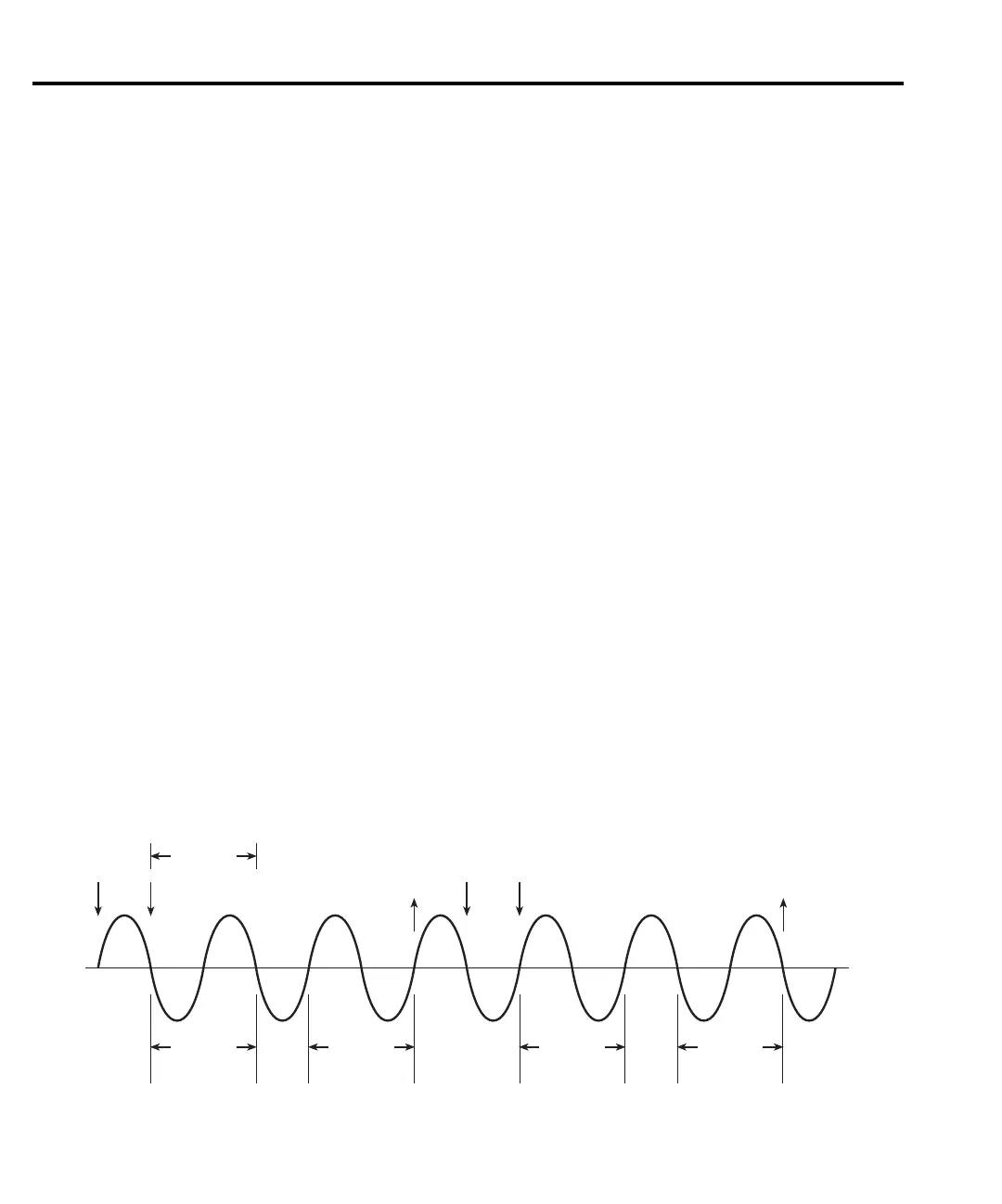
LSYNC (line cycle synchronization)
Synchronizing A/D conversions with the frequency of the power line increases common
mode and normal mode noise rejection. When line cycle synchronization is enabled, the
measurement is initiated at the first positive- or negative-going zero crossing of the power line
cycle after the trigger. Figure 2-1 shows the measurement process that consists of two A/D
conversions. If the trigger occurs during the positive cycle of the power line (as shown in
Figure 2-1), the first A/D conversion starts with the negative-going zero crossing of the power
line cycle. If the next trigger (Trigger #2) occurs during the negative cycle, then the
measurement process starts with the positive-going zero crossing.
Figure 2-1
Line cycle synchronization
A/D
Conversion
Phase A
1 PLC
Trigger
#1
A/D
Conversion
Phase B
A/D
Conversion
Phase A
A/D
Conversion
Phase B
Trigger
#2
Reading
Done
Reading
Done

 Loading...


