Voltage and Temperature Measurements 2-13
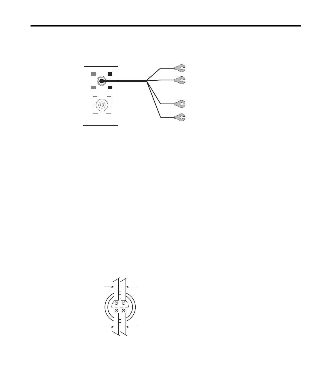
Figure 2-2
Model 2107 input cable
Voltage Connections — Mechanically connect (clamp) the cleaned copper lugs of the cable
to the cleaned copper connectors of the test circuit. For the test circuit, use clean #10 copper bus
wire wherever possible. Clean copper-to-copper connections minimize thermal EMFs which
could corrupt a measurement. See “Cleaning test circuit connectors” (located in this section).
If necessary, you can cut the copper lugs off the Model 2107 Input Cable and connect the
wires directly to your test circuit. If soldering, use silver solder to minimize thermal EMFs.
Temperature (Simulated Reference) Connections — For temperature measurements using
an external simulated reference junction, simply wrap (or clamp) the thermocouple wires around
the copper lugs (or bare wires) of the input cable.
Customized connections
Temperature measurements using the internal reference junction require that the
thermocouple wires be soldered directly to a LEMO connector that mates to the input of the
Model 2182. Silver solder should be used to minimize thermal EMFs. Figure 2-3 shows terminal
identification for a LEMO connector.
Figure 2-3
LEMO connector - terminal identification
Model
2107
Input
Cable
Red HI
Channel 1
Channel 2
Black LO
Green HI
White LO
2182
!
CHANNEL 1
HI
LO
CHANNEL 2
HI
LO
120V MAX
12V MAX
CAT I
350V PEAK ANY
TERMINAL TO CHASSIS
Channel 1 HI Channel 1 LO
Channel 2 HI Channel 2 LO
Rear View

 Loading...


