1-8 Performance Verification
Model 2700 verification
Perform these tests to verify accuracy using the Model 2700 front panel terminals.
Verifying DC voltage
Check DC voltage accuracy by applying accurate voltages from the DC voltage calibrator to
the Model 2700 INPUT jacks and verifying that the displayed readings fall within specified
limits.
CAUTION
Do not exceed 1000V peak between front terminals INPUT HI and
INPUT LO because instrument damage may occur.
Follow these steps to verify DC voltage accuracy:
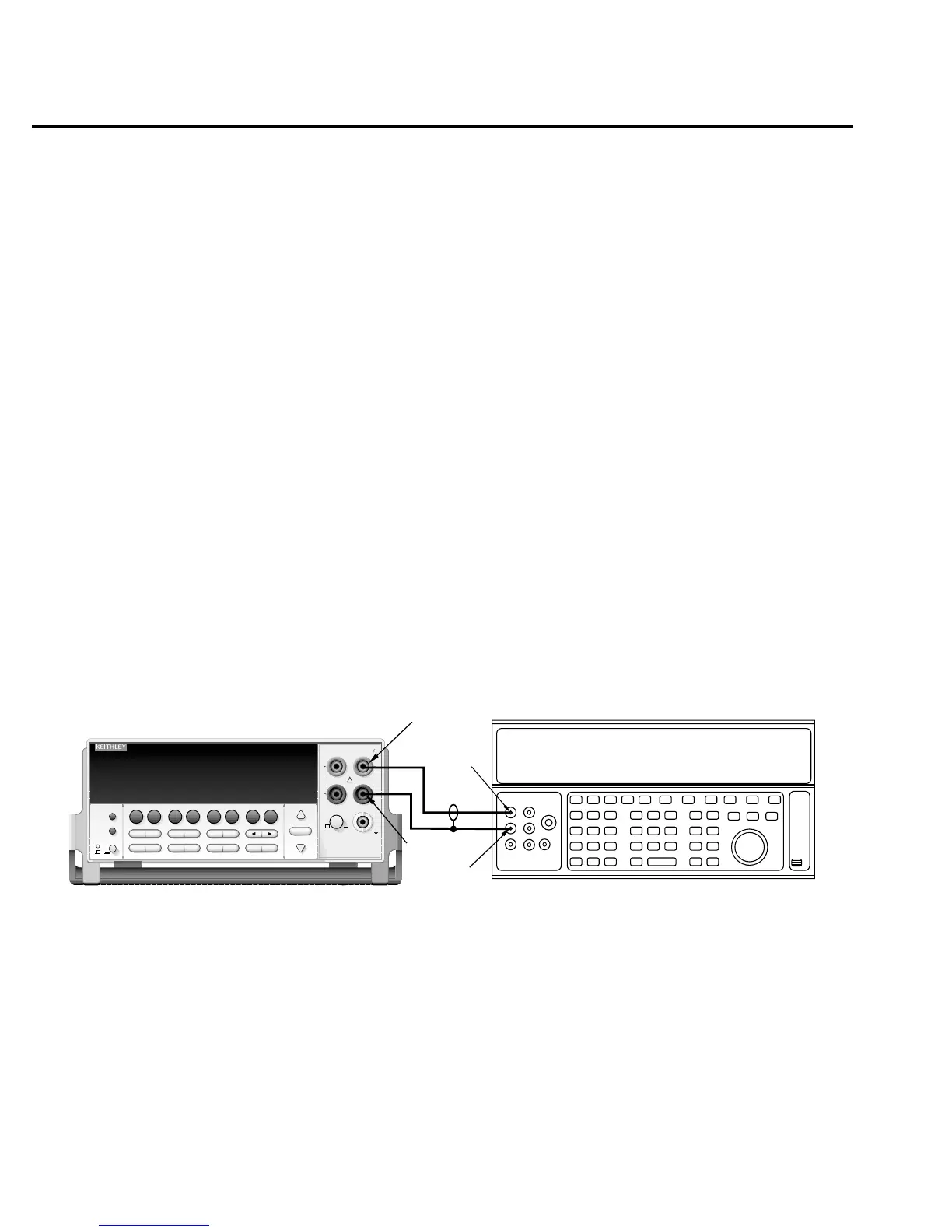
1. Connect the Model 2700 HI and LO INPUT jacks to the DC voltage calibrator as
shown in Figure 1-1. Make sure the INPUTS switch is set to the FRONT position.
NOTE
Use shielded, low-thermal connections when testing the 100mV and 1V ranges to
avoid errors caused by noise or thermal effects. Connect the shield to the calibra-
tor’s output LO terminal.
Figure 1-1
Connections for Model 2700 DC volts verification
2. Select the DC volts function by pressing the
DCV
key, and set the Model 2700 to the
100mV range.
3. Set the calibrator output to 0.00000mV DC, and allow the reading to settle.
4. Enable the Model 2700 REL mode. Leave REL enabled for the remainder of the DC
volts verification tests.
Output HI
Output
LO
Input
LO
Input HI
Calibrator (Output DC Voltage)
Note: Use shielded, low-thermal cables
for 100mV and 1V ranges.
Model 2700
Model 2700 Multimeter / Data Acquisition System
RANGE
!
F
500V
PEAK
FRONT/REAR
3A 250V
AMPS
HI
INPUT
LO
SENSE
Ω 4 WIRE
INPUTS
350V
PEAK
1000V
PEAK
AUTO
SHIFT
LOCAL
POWER
RANGE
R
EXIT ENTER
DIGITS RATE
RELFILTER
TRIG
EX TRIG
STORE
RECALL
OPEN
DCV
DCI
MATH
OUTPUT
RATIO
ACV
ACI
Ω2 Ω4
FREQ
TEMP
CH AVG
CONT
PERIOD SENSOR
LIMITS ON/OFFDELAY
HOLD
SAVE SETUP
CONFIG HALT
TYPE
LSYNC
TEST
MONITOR
STEP SCAN
OCOMP
CH-OFF CARD
CLOSE
Integra Series
RS-232
GPIB