Calibration 2-15
2. Perform the calibration steps summarized in Table 2-8. For each step:
• Set the calibrator to the indicated voltage, and make sure the unit is in operate.
(Use the recommended voltage if possible.)
• Send the indicated programming command. (Change the voltage parameter if you
are using a different calibration voltage.)
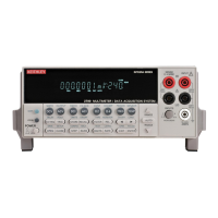
• Wait until the Model 2700 completes each step before continuing.
NOTE Ensure the calibrator has settled to the final value. You can do so by verifying that
the “Settled” indicator is off, or by using the *OPC? (operation complete) query.
Resistance calibration
Follow these steps for resistance calibration:
1. Set the calibrator to the resistance mode, and turn on external sensing.
NOTE Use external sense (4-wire Ω) when calibrating all resistance ranges. Be sure that
the calibrator external sense mode is turned on.
2. Perform the calibration steps summarized in Table 2-9. For each step:
• Set the calibrator to the indicated resistance, and make sure the unit is in operate.
(Use the recommended resistance or the closest available value.)
• Send the indicated programming command. (Change the command parameter if
you are using a different calibration resistance than that shown.)
• Wait until the Model 2700 completes each step before continuing.
Table 2-8
DC voltage calibration programming steps
Calibration step Calibrator voltage Calibration command* Parameter range
+10V
-10V
100V
+10.00000V
-10.00000V
100.0000V
:CAL:PROT:DC:STEP3 10
:CAL:PROT:DC:STEP4 -10
:CAL:PROT:DC:STEP5 100
9 to 11
-9 to -11
90 to 110
*Use recommended value where possible. Change parameter accordingly if using a different calibrator voltage.
Table 2-9
Resistance calibration programming steps
Calibration
step
Calibrator
resistance Calibration command* Parameter range
1kΩ
10kΩ
100kΩ
1MΩ
1kΩ
10kΩ
100kΩ
1MΩ
:CAL:PROT:DC:STEP6 1E3
:CAL:PROT:DC:STEP7 10E3
:CAL:PROT:DC:STEP8 100E3
:CAL:PROT:DC:STEP9 1E6
900 to 1.1E3
9E3 to 11E3
90E3 to 110E3
900E3 to 1.1E6
*Use exact calibrator resistance value for parameter.

 Loading...