1-26 Performance Verification
7. Source the nominal full-scale resistance values for the 100Ω-10MΩ ranges summarized
in Table 1-13, and verify that the readings are within calculated limits.
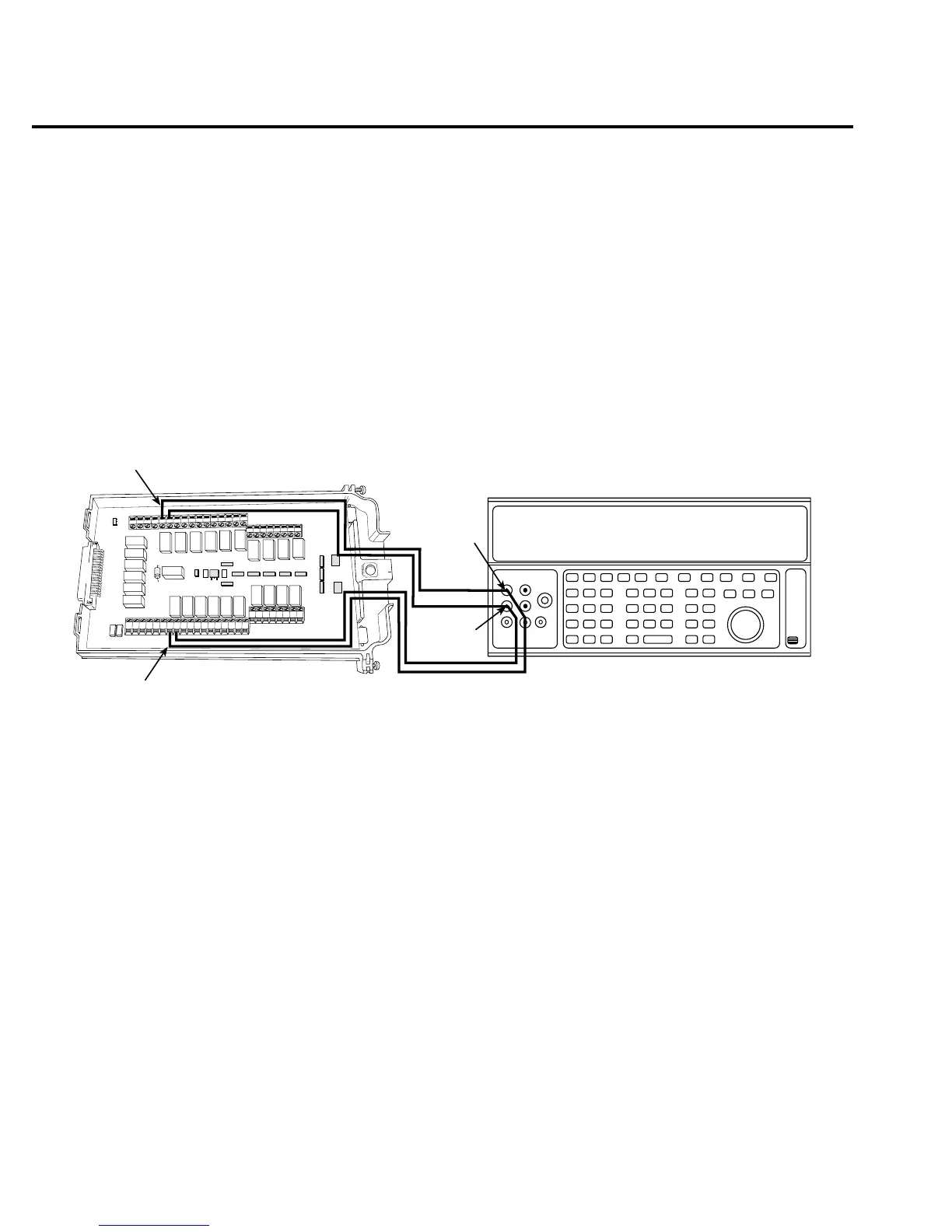
8. Connect the Model 7700 CH1 and CH11 terminals to the calibrator as shown in
Figure 1-13.
9. Disable external sense on the calibrator.
10. Set the Model 2700 for the 100MΩ range.
11. Source a nominal 100MΩ resistance value, and verify that the reading is within calcu-
lated limits for the 100MΩ range.
12. Press the OPEN key to open Channel 1.
Figure 1-13
Connections for Model 7700 resistance verification (100MΩ range)
HLHL
AMPS
HLHLHLHLHLHL
LO
CH21 CH22 CH11 CH12 CH13 CH14 CH15 CH16
HLHLHLHL
CH17 CH18 CH19 CH20
SENSE
(OHMS, 4 WIRE)
INPUT
(V, 2 WIRE)
HLHLHLHL
CH7 CH8 CH9 CH10
HLHL
HLHL
HLHL
HLHL
INPUT SENSE
CH1 CH2
CH3
CH4
CH5
CH6
CH1
CH11
Output
HI
Output
LO
Calibrator (Output 2-wire Resistance)
Note: Use shielded cables to minimize
noise. Disable calibrator external
sense mode.
Model 7700