Performance Verification 1-17
4. Set the decade resistance box to each of the values shown in Table 1-8, and verify that
the temperature readings are within the required limits.
Verifying frequency
Follow the steps below to verify the Model 2700 frequency function:
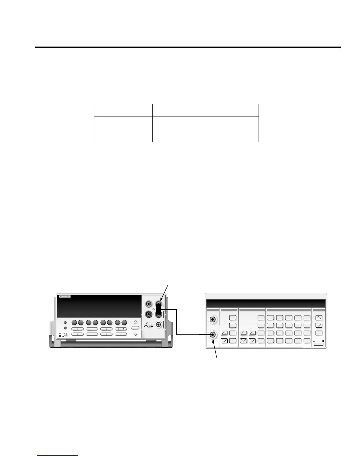
1. Connect the function generator to the Model 2700 INPUT jacks. (See Figure 1-7.) Be
sure the INPUTS switch is in the FRONT position.
2. Set the function generator to output a 1kHz, 1V RMS sine wave.
3. Select the Model 2700 frequency function by pressing the FREQ key.
4. Verify that the Model 2700 frequency reading is between 999.9Hz and 1.0001kHz.
Figure 1-7
Connections for Model 2700 frequency verification
Table 1-8
Four-wire RTD temperature verification reading limits
Applied resistance* Reading limits (1 year, 18°C to 28°C)
22.80Ω
100.00Ω
313.59Ω
-190.06 to -189.94°C
-0.06 to +0.06°C
599.94 to 600.06°C
*Based on α = 0.00385. See text.
Function Generator
Model 2700
Model 2700 Multimeter / Data Acquisition System
RANGE
!
F
500V
PEAK
FRONT/REAR
3A 250V
AMPS
HI
INPUT
LO
SENSE
Ω 4 WIRE
INPUTS
350V
PEAK
1000V
PEAK
AUTO
SHIFT
LOCAL
POWER
RANGE
R
EXIT ENTER
DIGITS RATE
RELFILTER
TRIG
EX TRIG
STORE
RECALL
OPEN
DCV
DCI
MATH
OUTPUT
RATIO
ACV
ACI
Ω2 Ω4
FREQ
TEMP
CH AVG
CONT
PERIOD SENSOR
LIMITS ON/OFFDELAY
HOLD
SAVE SETUP
CONFIG HALT
TYPE
LSYNC
TEST
MONITOR
STEP SCAN
OCOMP
CH-OFF CARD
CLOSE
Integra Series
RS-232
GPIB
BNC-to-Dual
Banana Plug
Adapter
50Ω
Coax
Cable
Function
Output