Display
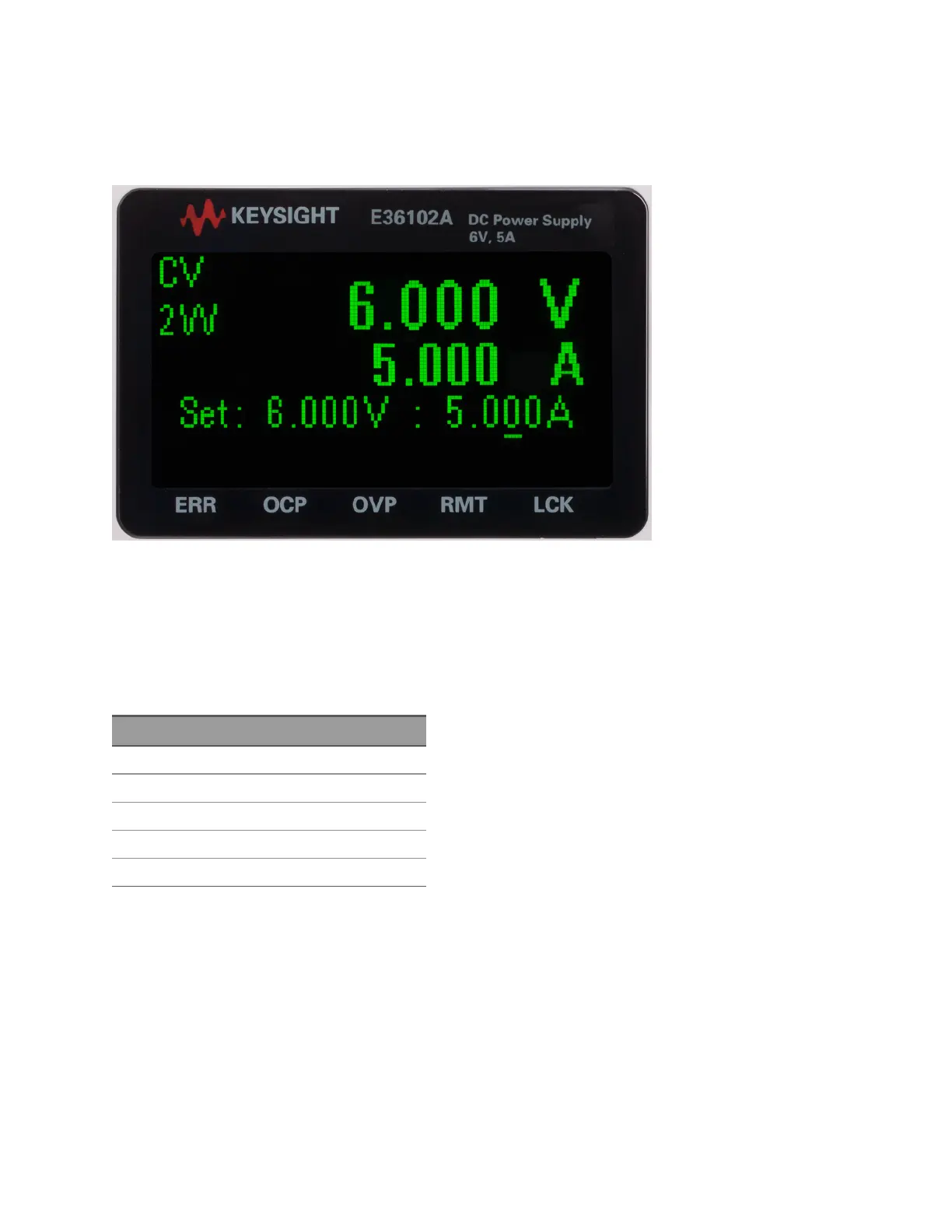
The power supply's front panel features a high-visibility OLED display.
The upper left corner of the display shows either CV or CC to indicate that the instrument is in constant
voltage or constant current mode. Below that is either 2W or 4W, to indicate whether 2-wire (normal)
or 4-wire (remote sensing) measurement is in use. The right side of the display shows the output voltage
and current (when the output is enabled), and the voltage and current settings are shown near the
bottom of the screen.
The very bottom of the screen can show arrows, each of which represents a different annunciator.
Label Meaning
ERR An error has occurred.
OCP An overcurrent protection event has occurred.
OVP An overvoltage protection event has occurred.
RMT The instrument is being programmed remotely.
LCK The front panel is locked.
To Set up the Instrument
Place the instrument's feet on a flat, smooth horizontal surface. Connect output and sense leads to the
front panel, being careful not to short the leads together. Attach the power cable to the rear panel, then
plug it into main power. Connect LAN or USB cables as desired, and you may also secure the instrument
with a security lock cable.