1.
Turn off the power supply using the AC line switch.
2.
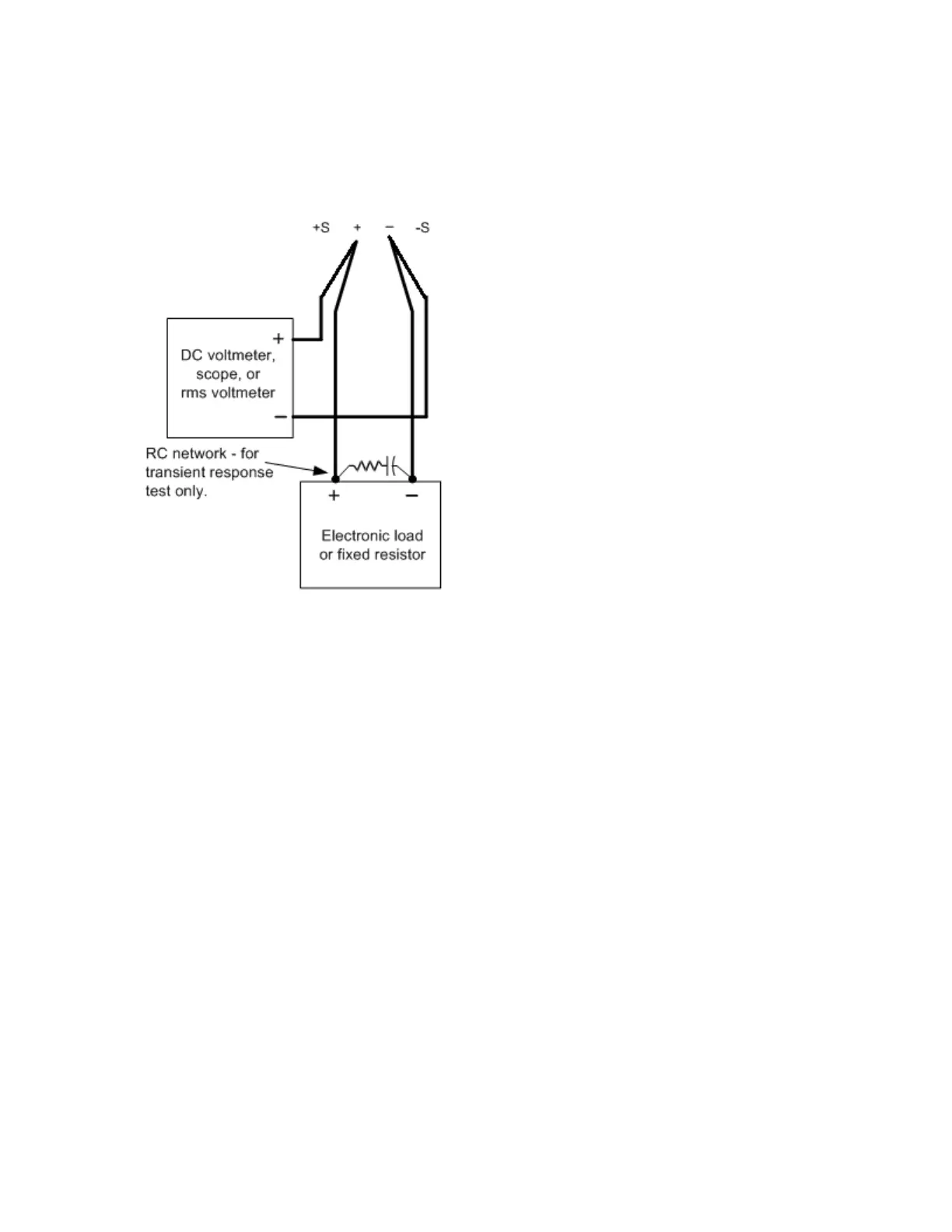
Connect an oscilloscope and electronic load between the (+) and (–) terminals of the output to be
tested as shown below.
3.
If you are using a PC to control the power supply, connect a LAN or USB cable from the power sup-
ply to the PC.
4.
Turn on the power supply using the AC line switch.
5.
Set the instrument settings as described in the test record form under “Transient Response”. See
the Test Record Forms under “Transient Response” for details. Enable the output.
6.
Operate the electronic load in constant current mode and set its current to the value in the test
record form under “Transient Response”. See the Test Record Forms under Test Description of “Tran-
sient Response” for details. Set the transient level to ½ the maximum current. Set the transient duty
cycle to 50% and transient frequency to 1 kHz. Check that the front panel CV annunciator of the
power supply remains lit. If it turns to CC or UNREG, adjust the maximum current load so that the
output current drops slightly until the CV annunciator lights up.
7.
Adjust the oscilloscope to display transients as shown below. Note that the pulse width (t2-t1) of the
transient at the voltage settling band, for example 15 mV for the E36102 from the base line is no
more than 50 ms.