Keysight PXIe Chassis Family User Guide 95
Chassis Trigger Lines Configuring the PXI Trigger Bus
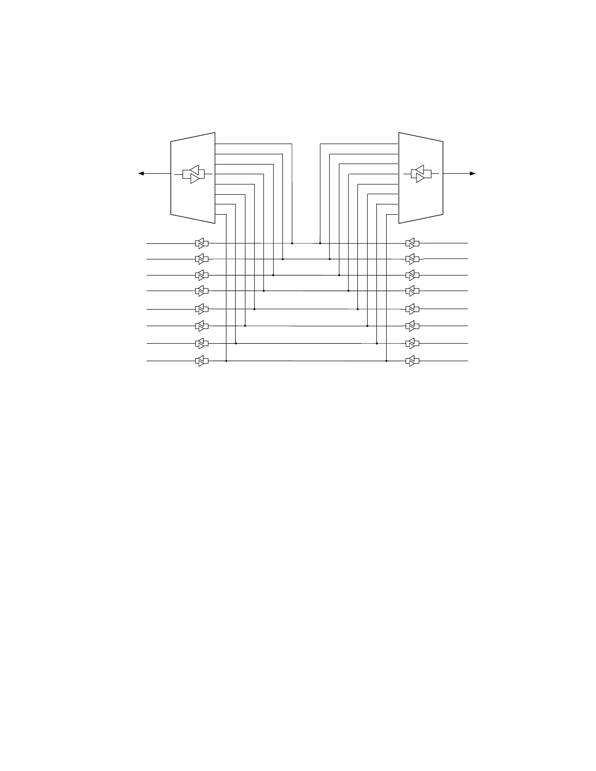
The preceding figure illustrates a possible front panel Trigger Port configuration
using a wiring diagram. In this configuration, both Trigger Ports are connected to
Trigger Bus Segment 2.
The ports are always enabled; changing the drive type takes effect immediately.
Because it is possible that a configuration change can cause a signal to be
placed on a trigger line, it is recommended that you deactivate your test system
when making front panel Trigger Port configuration changes.
When the Trigger Port is set to Input, the default configuration is “none” for the
connection to PXI_TRIG[0:7] trigger signal lines.
When the front panel Trigger Port is set to Output, it is of type Push-Pull Output.
For the M9018B and M9019A, if you want to connect the front panel trigger
ports to Trigger Bus Segment 1, you must use Connection Expert to configure
trigger routes between Trigger Bus Segment 1 and Trigger Bus Segment 2.
Figure 46 Wiring diagram illustration of an example front panel Trigger Port configuration.
PXI TRIG0
Trigger Bus
Segment 1
Trigger Bus
Segment 2
Trigger Bus
Segment 3
PXI TRIG1
PXI TRIG2
PXI TRIG3
PXI TRIG4
PXI TRIG5
PXI TRIG6
PXI TRIG7
Trig 1
(Chassis Front Panel)
Trig 2
(Chassis Front Panel)
8 to 1
MUX
8 to 1
MUX
Input &
Push Pull
Output
Input &
Push Pull
Output