94 Keysight PXIe Chassis Family User Guide
Configuring the PXI Trigger Bus Chassis Trigger Lines
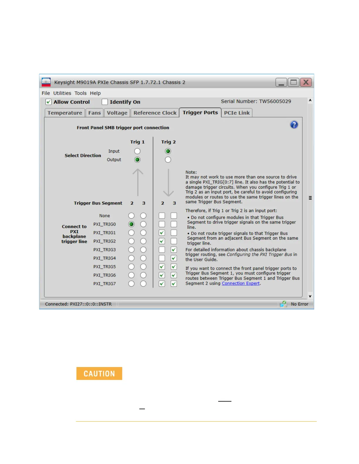
The preceding figure shows Trig Port 1 as an Output from PXI_TRIG0 on Trigger
Bus Segment 2 and Trig Port 2 as an Input to multiple PXI_TRIG lines on both
Segment 2 and 3.
There can be only one source for a Trigger Signal.
Figure 45 M9019A SFP example configuration of the front panel Trigger Ports.
When configuring either Trig 1 or Trig 2 as an Input Port:
- Do not configure PXI or PXIe modules in the same Trigger Bus
segment to generate trigger signals on the same trigger line.
- Do not route trigger signals from
another Trigger Bus segment
to
the segment connected to Trig 1 and Trig 2 on the same
trigger line.