Keysight PXIe Chassis Family User Guide 97
Front Panel Trigger Port Configuration Guidelines Configuring the PXI Trigger Bus
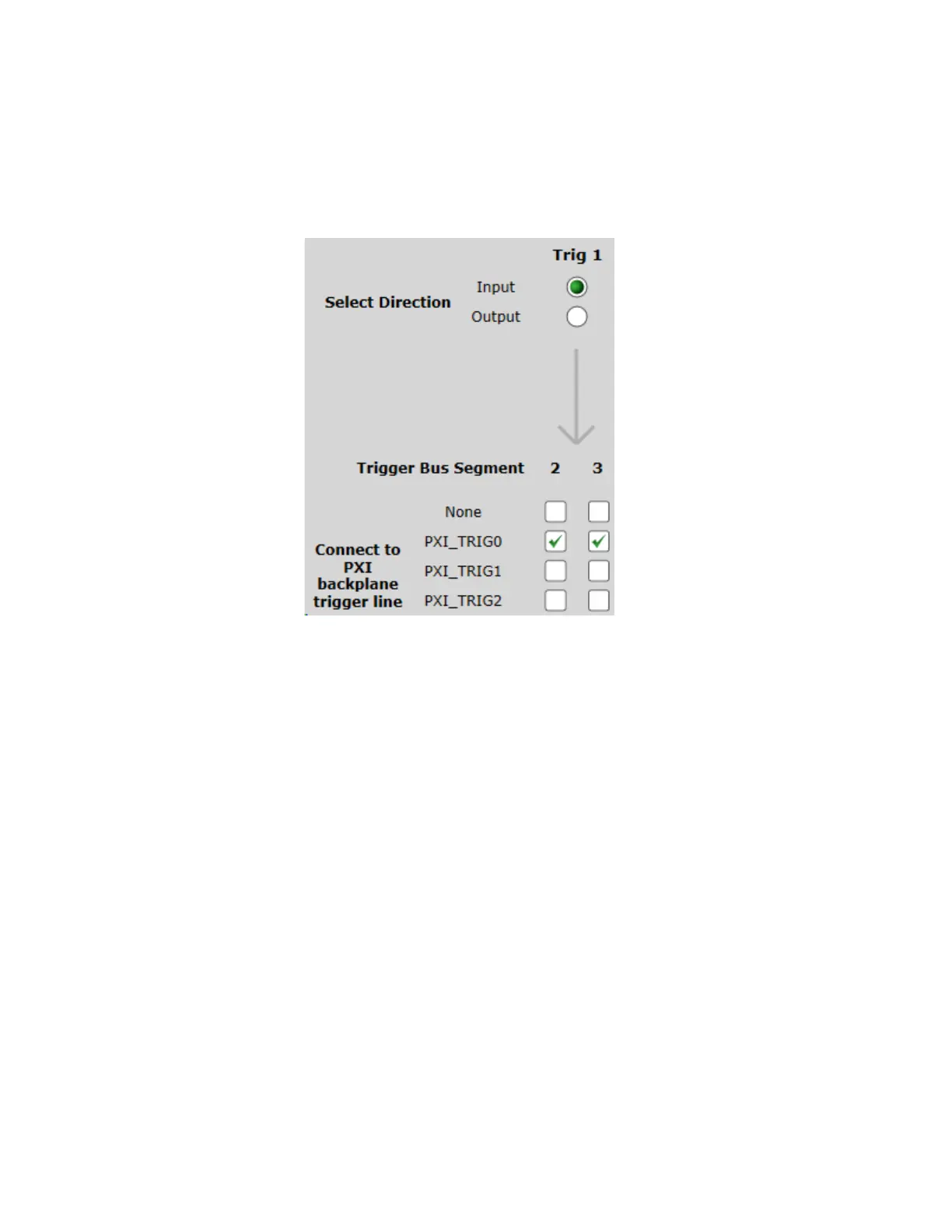
The following figure is a section of the SFP Trigger Ports tab, showing both boxes
checked so that the front panel Trig 1 signal arrives on PXI_TRI0 on both Trigger
Bus Segments 2 and 3.
You cannot use a route to propagate the Input Trigger signal between Bus
Segments 2 and 3. If you configure a route, the Front Panel Trigger Input trigger
signal is silently disabled.
Figure 47 M9019A SFP example configuration of Trig 1 to PXI_TRIG0 on Segment 2 and 3.