Keysight NFA Series Noise Figure Analyzers Service Guide 427
Assembly Replacement Procedures
L.O. Synthesizer Assembly
L.O. Synthesizer Assembly
Removal
1. Remove the instrument outer case. Refer to the “Instrument Outer Case”
removal procedure.
2. Remove the instrument top brace. Refer to the “Top Brace” removal
procedure.
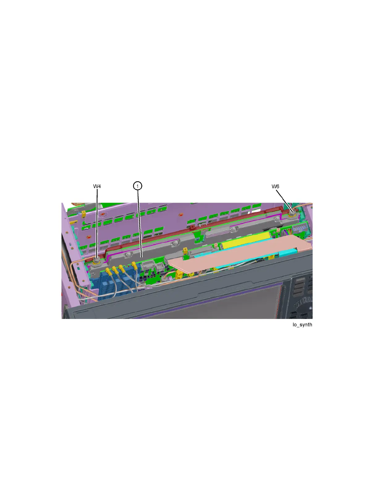
3. Refer to Figure 15-28. Remove the cables W4 and W6 from the L.O.
Synthesizer assembly (1) using the 5/16 inch wrench.
4. The L.O. Synthesizer assembly can now be unplugged from the
motherboard by pulling up on the board and lifted out of the chassis.
Figure 15-28 L.O. Synthesizer Assembly Removal
Replacement
1. Refer to Figure 15-28. Install the L.O. Synthesizer assembly into slot 5 in
the chassis and press down to plug it into the motherboard.
2. Reattach the cables W4 and W6 to the L.O. Synthesizer assembly (1).
Torque to 10 inch-pounds.
3. Replace the instrument top brace. Refer to the “Top Brace” replacement
procedure.
4. Replace the instrument outer case. Refer to the “Instrument Outer Case”
replacement procedure.