458 Keysight NFA Series Noise Figure Analyzers Service Guide
Assembly Replacement Procedures
Front Frame Assembly
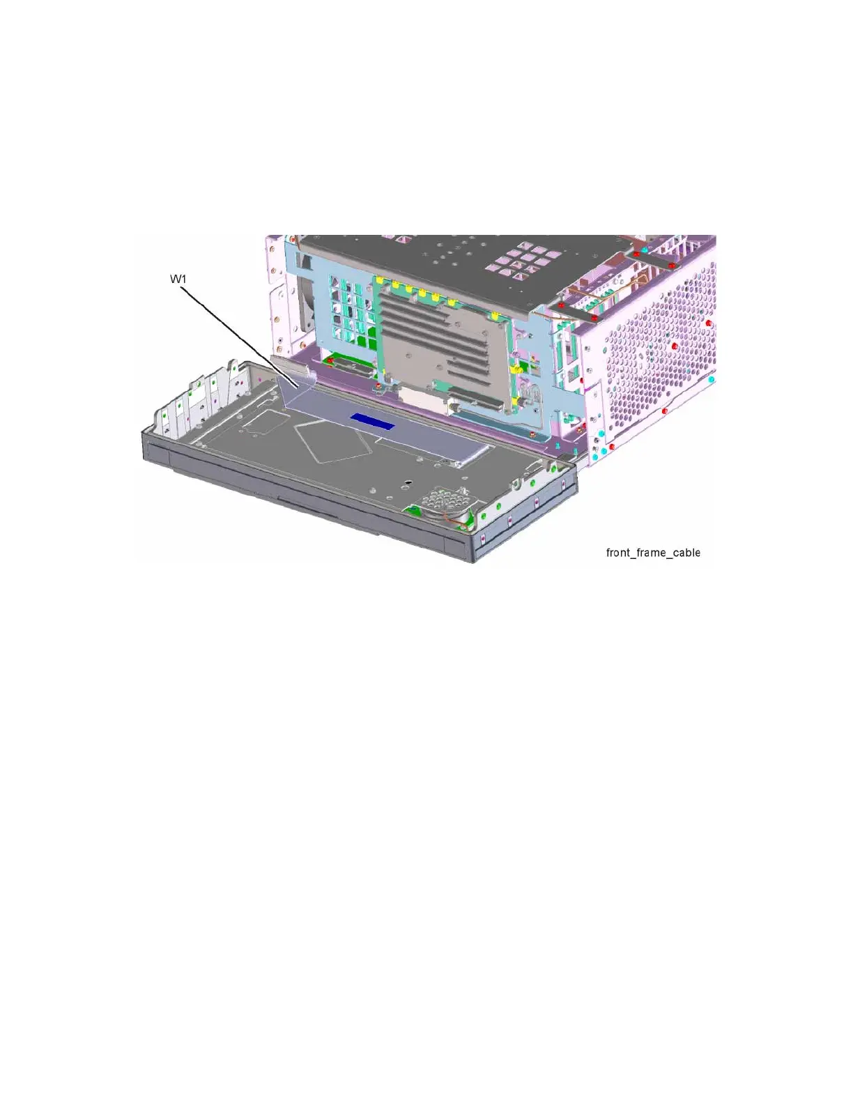
4. Refer to Figure 15-52. Pull the Front Frame Assembly carefully away from
the chassis. Remove the ribbon cable W1 from the mother board.
Figure 15-52 Front Panel Cable
Replacement
1. Reattach the ribbon cable W1.
2. Refer to Figure 15-51. Carefully position the Front Frame Assembly onto
the chassis. Ensure no cables are crushed. Replace the eight screws (1),
four on each side of the chassis. Torque to 9 inch pounds.
3. If Option EXM, External Mixing, is installed attach semi-rigid LO/IF cable.
Torque to 10 inch-pounds.
4. Replace the outer case. Refer to the “Instrument Outer Case” replacement
procedure.