430 Keysight NFA Series Noise Figure Analyzers Service Guide
Assembly Replacement Procedures
Reference Assembly
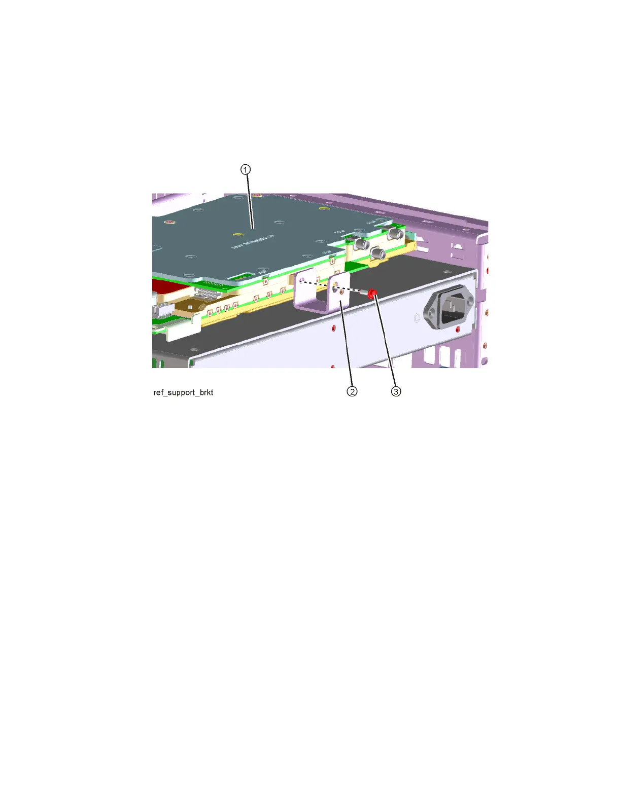
5. Refer to Figure 15-31. Remove the reference support bracket (2) by
removing the pan-head screw (3 ) (0515-0372) securing the bracket to the
Reference assembly (1).
Figure 15-31 Reference Support Bracket Removal
6. The reference assembly can be removed from the chassis by leveraging up
on the ejector and pulling the board out on the other side.
Replacement
1. Slide the reference assembly into the slot at the rear of the instrument and
push on the assembly to mate the connectors to the midplane assembly.
Secure with the ejector.
2. Refer to Figure 15-31. Secure the reference support bracket (2) to the
Reference assembly (1) using a pan-head screw (3) (0515-0372).
3. Refer to Figure 15-31 and Figure 15-30. Reconnect the cables to the
correct locations. Torque the semi-rigid coax cables to 10 inch-pounds.
4. Replace the rear panel. Refer to the “Rear Panel” replacement procedure.
5. Replace the top brace. Refer to the “Top Brace” replacement procedure.
6. Replace the instrument outer case. Refer to the “Instrument Outer Case”
replacement procedure.