Keysight NFA Series Noise Figure Analyzers Service Guide 455
Assembly Replacement Procedures
Input Connector Assembly
Input Connector Assembly
Removal
1. Remove the instrument outer case. Refer to the “Instrument Outer Case”
removal procedure.
2. Remove the Front Frame Assembly. Refer to the “Front Frame Assembly”
removal procedure.
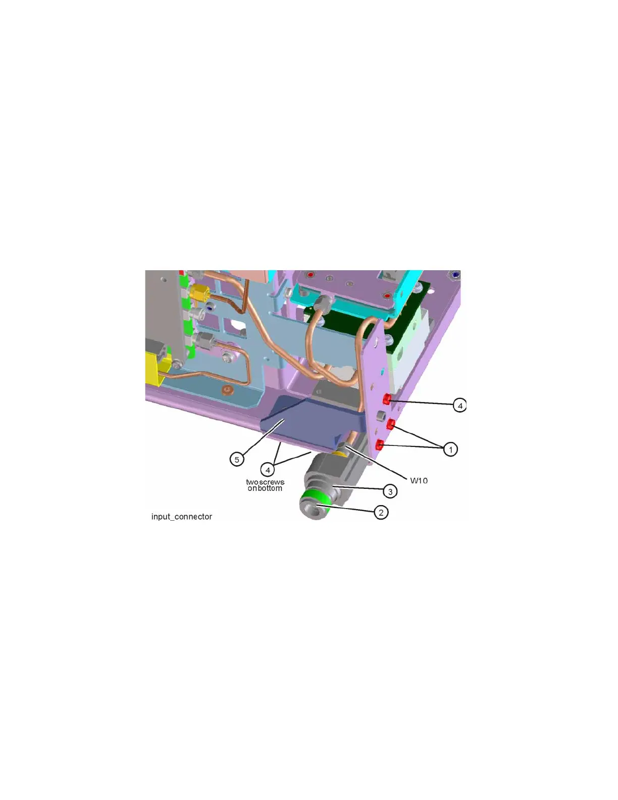
3. Refer to Figure 15-50. Disconnect the semi-rigid cable W10 from the Input
Connector Assembly (2).
Figure 15-50 Input Connector Assembly Removal
4. Remove the two screws (1) that attach the Input Connector Assembly
(2) to the chassis. The connector assembly can now be lifted from the
chassis.
5. To remove the gusset (5) remove the three screws (4), one on the side of
the chassis and two on the bottom.