Keysight NFA Series Noise Figure Analyzers Service Guide 57
Boot Up and Initialization Troubleshooting
Potential Problems During Boot Process
If no:
Replace the A6 Power Supply assembly.
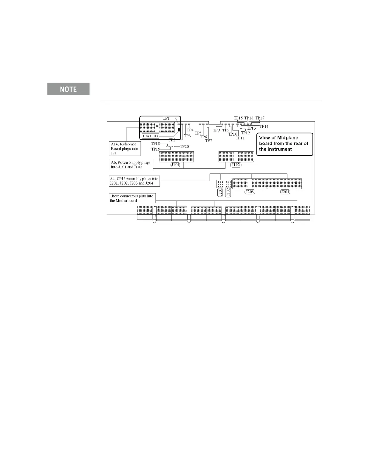
Figure 2-5 A7 Midplane Board - Fan LED
6. With the instrument turned off, and the AC power cord removed, remove
the Fan Assembly including unplugging both fans from the A8
Motherboard. Refer to Chapter 15, “Assembly Replacement Procedures”,
on page 389 in this manual.
7. Turn the instrument power back on and measure the fan voltage at both of
the fan connectors (J6 & J7) on the A8 Motherboard.
Both connectors have three pins. The outer conductors on both
connectors are the FAN_P supply and the center conductors are FAN_N.
The voltage between FAN_P and chassis ground should be between +7
and +15 VDC on both connectors.
Does the A8 Motherboard fan connector for the fan(s) that do not work
have the required voltage level?
If yes:
Replace the fan(s) that is not working
If no:
After verifying that the connections between the A7 Midplane board
and the A8 Motherboard are mechanically and electrically secure
replace the A8 Motherboard.
Before replacing the power supply, verify the midplane and motherboard
interconnects are mechanically secure.