2 Front and Rear Panel Features
Front-Panel Features
Item
Description
# Name
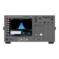
14 Input 2
1.0 mm (m)
Connector for inputting external signals 3 Hz to upper range of
the analyzer. Make sure that the total power of all signals at
this analyzer input does not exceed +5 dBm (3.16 mW) with 0 dB
attenuation.
15 Power Standby/ On
Turns the analyzer on. A green light indicates power on. A
yellow light indicates standby mode.
The front-panel switch is a standby
switch, not a LINE switch
(disconnecting device). The analyzer
continues to draw power even when the
front-panel switch is in standby.
The main power cord can be used as
the system disconnecting device. It
disconnects the mains circuits from the
mains supply.
22 Getting Started and Troubleshooting Guide
 Loading...


