16
Index Towers and Camber Tube
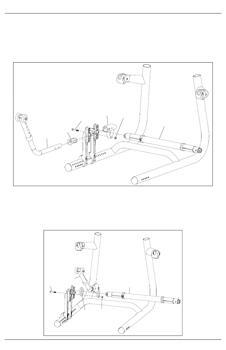
5. When standard anti-tips are present - Install the anti-tip mount (D) onto the upper base mount with bolt
(C) and nut (E) using a 4mm Allen wrench and a 2.5mm wrench. Do not fully tighten until full camber
tube assembly is complete.
6. Install the anti-tip assembly (A) into the anti-tip sleeve (B). Install the anti-tip assembly and sleeve into
the anti-tip mount and ensure index button "clicks" and locks into one of the holes in the anti-tip
mount.
7. Install the camber tube (F) into the opening in the anti-tip mount.
8. When user activated anti-tips are present - Install the anti-tip spacer (C) and anti-tip assembly (B) onto
the upper base mount with bolt (A) and nut (D) using a 4mm Allen wrench and a 2.5mm wrench. Do not
fully tighten until full camber tube assembly is complete.
9. Install the camber tube (E) into the opening in the anti-tip mount.
NOTE: Ensure the camber tube is perpendicular to the seat frame rails. Ensure the towers and
clamps are aligned identically on both sides.