51
Anti-Tips
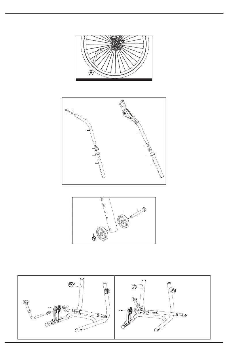
NOTE: To ensure safe use, verify that the distance between the footplate and the ground is greater
than or equal to 2.5" and always look ahead for potential obstructions or surface transitions.
NOTE: After any adjustment, ensure anti-tips clear the wheels as shown below.
1. Assemble the anti-tip by sliding the anti-rattle bushing on (D) and connecting the two anti-tip tubes (B
& C), ensuring they "click" together when the detent buttons (A) engage.
2. Install the wheels (B) onto the anti-tip tube with a bolt (C) and nut (A) using two 10mm wrenches.
3. The anti-tip receivers are installed on the base mounts and the camber tube runs through the receivers.
The standard and user activated configurations are shown below. For more specific information, refer
to the Index Towers and Camber Tube section in this technical manual.
NOTE: The anti-tip receiver would never be mounted upside down, even when OAD is present.
A
A
B
C
C
B
A
D
D
Standard Anti-Tip
User Activated Anti-Tip
Standard Anti-Tips
User Activated Anti-Tips