diagram below for terms that are commonly used during the process of adjusting the chairs.
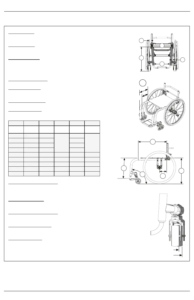
A. Seat Width
See Diagram 1
Measured from outside of frame tube on one side to outside of
frame tube on other side.
B. Seat Depth
See Diagram 3
Measured from front of back posts to front edge of seat sling. Seat
sling starts at beginning of bend at front of frame.
C. Sling Position
See Diagram 2
In Performance Position (0”), sling is at front of frame to keep chair
shorter and more maneuverable. The 1” or 2” seat sling position
extends the frame in front of the sling by that amount. Adding more
frame can improve stability and provide support to aid in transfers.
D. Front Frame Bend
See Diagram 3
Angle between front seat tube and ground.
Seat Width Straight 1” Y Taper 2” Y Taper 3.5° V Taper 7° V Taper
Outside
Measurement
2” Narrower than
Seat Width
4” Narrower than
Seat Width
6” Narrower than
Seat Width
4” Narrower than
Seat Width
6” Narrower than
Seat Width
12” 9.5” 7.5” 7.5”
13” 10.5” 8.5” 8.5”
14” 11.5” 9.5” 9.5”
15” 12.5” 10.5” 10.5”
16” 13.5” 11.5” 9.5” 11.5” 9.5”
17” 14.5” 12.5” 10.5” 12.5” 10.5”
18” 15.5” 13.5” 11.5” 13.5” 11.5”
19” 16.5” 14.5” 12.5” 14.5” 12.5”
20” 17.5” 15.5” 13.5” 15.5” 13.5”
F. Front Seat Height
See Diagram 1
Measured from floor to top of seat tube at front of seat sling.
G. Footrest Width
See Diagram 1
Measured from inside of front tube to inside of front tube on other
side. Footrest width is listed below for each seat width and taper.
E. Footrest Taper
See Diagram 1
Indicates bend of front frame creating footrest. Taper is measured
from outside of seat frame to outside of front tube.
H. Seat to Footrest Length
See Diagram 3
Measured from front edge of seat sling to top rear of footrest.
Footrest length of at least 2.5” shorter than front seat height
recommended.
I. Rear Seat Height
See Diagram 3
Measured from floor to top of seat tube at front of back post. Rear
seat height is custom to needs.
J. Center of Gravity Preset
See Diagram 3
Measured from front of back post to center of rear axle. 0”
indicates axle will be directly under back post.
K. Rear Wheel Spacing
See Diagram 1
Measured from outside of seat back to inside of rear tire. Adjustable
out .5” from setting.
L. Caster Position
See Diagram 4
The Optimized Position keeps the casters tighter to the frame for
enhanced maneuverability. Expanded Position pushes the casters
out .75” past the Optimized Position for increased stability.
Diagram 1
A
G
F
K
E
A
G
E
F
K
Diagram 2
Classic
Performance
C
Diagram 3
I
B
D
J
H
Diagram 4
Optimized
Expanded