68
Growing Your Rogue XP in Width
NOTE: Visit the tutorial page at kimobility.com for the growth adjustment video.
It is recommended that you follow the below sequence of adjustments when growing your Rogue XP in
width.
Remove the following assemblies from chair in order listed:
1. Upholstery - See seat upholstery section on page 38.
2. Backrest Release Cable - See backrest assembly section on page 19. Use the section that
corresponds with the backrest assembly style found on the chair.
3. Rigidizer Bar - See back post section which begins on page 23. Use the section that corresponds with
the back post style found on the chair.
4. Footrest Assembly - See footrest section which begins on page 45. Use the section that corresponds
with the footrest assembly style found on the chair.
5. Camber Tube - See camber mount assembly and camber tube and adapters section which begins on
page 15.
Replace new assemblies for width adjustment in reverse of order listed above. Reference removal and
replacement instructions.
Tipping Lever
Installation
NOTE: For wheel sizes 20 and 22 the short tipping lever is used. For wheel sizes 24, 25 and 26 the
standard tipping lever size is used.
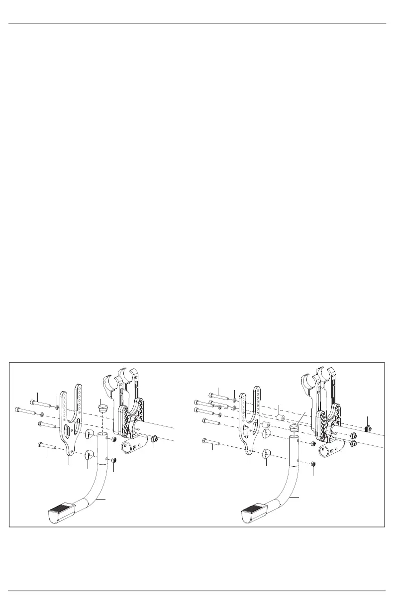
1. Install the tipping lever (F) to the adapter plate (H) with two bolts (I), two saddles (G) and two nuts (E)
using two 10mm wrenches.
2. Install the adapter plate assembly to the chair with two or four bolts (A), two or four lock washers (B),
two spacers (J - not used in lowest tower position) and two or four square nuts (D) using a 5mm Allen
wrench.
3. Install the end plug (C) into the tipping lever.
4. Repeat on opposite side.
A
B
C
D
E
F
G
H
I
A
B
C
G
H
I
D
E
F
J
Standard Mount
with Spacers
Standard Mount in
Lowest Tower
Position (No Spacers)


 To Next Page