PLZ-U Installation and Preparation 2-13
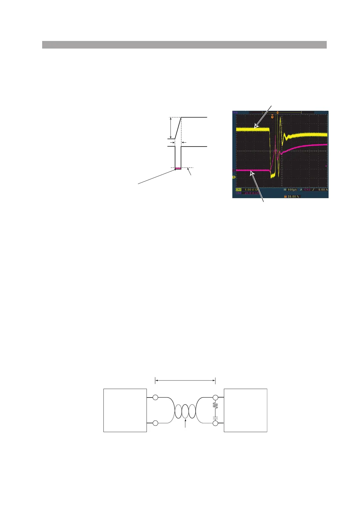
When the value of instantaneous voltage drops under the minimum operating voltage
depends on the generated voltage at the load input terminal, the response of recovery will
be extensively delayed. In such event, the electronic load (PLZ-U) may generate unstable
oscillation or becomes into the hunting operation.
In such condition, the input voltage
may exceed the maximum input voltage and cause damage to the PLZ-U.
Fig. 2-8 Waveform example: Generate unstable oscillation or hunting
operation
You must be careful especially when the slew rate setting is high or switching is per-
formed using large currents through parallel operation.
To prevent problems, connect the PLZ-U and the equipment under test using the
shortest twisted wire possible to keep the voltage caused by inductance between the
minimum operating voltage and the maximum input voltage range or set a low slew
rate.
If the high-speed response operation is not required, decrease the slew rate setting.
In such settings, the value of DI /DT will be decreased, accordingly the generated
voltage will be reduced even the inductance of load wiring can not be reduced.
In the case of DC operation also, the phase delay of the current may cause instabil-
ity in the PLZ-U control inducing oscillation. In this case also, connect the PLZ-U
and the equipment under test using the shortest twisted wire possible.
If only DC operation is required, a capacitor and a resistor may be connected to the
load input terminal as shown in Fig. 2-9 to alleviate oscillation. In this case, use the
capacitor within its allowable ripple current.
Fig. 2-9 Length of wiring
Current
Voltage at Load Input Terminal
Minimum operating voltage
When the voltage drops under minimum
operating voltage, the electronic load may generate
unstable oscillation or becomes into hunting operation.
ΔT
ΔI
Example of waveform
Voltage at the load input terminal
Current
Equipment
under test
PLZ-U Series
Keep the wire short
Twist
–
–
+
+
R
C
Example: R = 10 Ω and
C = 100 μF

 Loading...