5-1
COMPONENT TESTING
Before testing any of the components, perform
the following checks:
• The most common cause for control failure is
corrosion on connectors. Therefore, discon-
necting and reconnecting wires will be nec-
essary throughout test procedures.
• All tests/checks should be made with a VOM
or DVM having a sensitivity of 20,000 ohms-
per-volt DC, or greater.
• Check all connections before replacing com-
ponents, looking for broken or loose wires,
failed terminals, or wires not pressed into
connectors far enough.
• Resistance checks must be made with power
cord unplugged from outlet, and with wiring
harness or connectors disconnected.
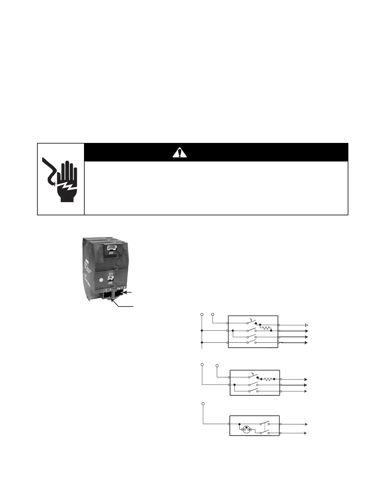
WARNING
Electrical Shock Hazard
Disconnect power before servicing.
Replace all parts and panels before operating.
Failure to do so can result in death or electrical shock.
INFINITE (SMART) SWITCH
L1a / L1 / N
D / S (DUAL)
S (SINGLE)
Refer to page 4-4 for the procedure for servic-
ing an infinite switch.
1. Unplug range or disconnect power.
2. Disconnect the wire connectors from the
infinite switch.
3. Set the ohmmeter to the R x 100 scale.
4. Touch the ohmmeter test leads to the
infinite switch connector pins as follows:
Switch Off: L1a to 2 = open circuit (∞ )
Switch On: L1a to 2 = closed circuit (0 Ω)
Switch Off: L1a to 1 = open circuit (∞ )
Switch On: L1a to 1 = closed circuit (0 Ω)
DUAL & SINGLE INFINITE &
WARMING DRAWER SWITCHES
MODELS: KESV808, KESV908, &
KESI901
NOTE: These switches are not included in this
Job Aid, but are standard switches found on
the model ranges listed above. A wiring dia-
gram for each switch is shown below.
TO LIMITER 2A
TO LIMITER 2A
TO NEUTRAL
TO L1 (INNER ELEMENT)
TO L1 (ELEMENT)
TO 2B ON ELEMENT
TO L2 (OUTER ELEMENT)
TO INDICATOR LIGHT
TO INDICATOR LIGHT
H1
H2
LR
Y/W
BU
Y
L1
L2
P
R
L1
L1
L2
L2
BK
4
2
LF
OR/W
OR/BK
OR
S2
P1
S1
P2
4A
BK
BK
L1
BK
R
BU
2
GY
W
3
1
WARM
DUAL INFINITE SWITCH
SINGLE INFINITE SWITCH
WARMING DRAWER SWITCH