5-4
ELEMENTS & LIMITERS
Refer to page 4-8 for the procedure for servic-
ing the elements & limiters.
NOTE: The elements shown below are tested
at their terminal locations. The dual elements
can also be checked at the infinite switches,
pins 1 and 2.
1. Unplug range or disconnect power.
2. Remove the cooktop glass (see page 4-5
for the procedure).
3. Disconnect one of the wires from the ele-
ment terminals.
4. Set the ohmmeter to the R X 1 scale.
5. Touch the ohmmeter test leads to the ele-
ment terminals as follows:
LF & (RR)—(Dual Elements)
• OR-WH and OR-BK (BU-WH and
BU-BK) = 91 to 96 Ω
• OR-BK and BK (BU-BK and BK)
= 32 to 44 Ω
6. To test a limiter:
a) Touch the ohmmeter test leads to lim-
iter terminals 1A & 2A. The meter
should indicate continuity (0 Ω).
b) Touch the ohmmeter test leads to lim-
iter terminals 1B & 2B.
With the temperature below 150˚F, the
meter should indicate an open circuit
(infinite).
With the temperature above 150˚F, the
meter should indicate continuity (0 Ω).
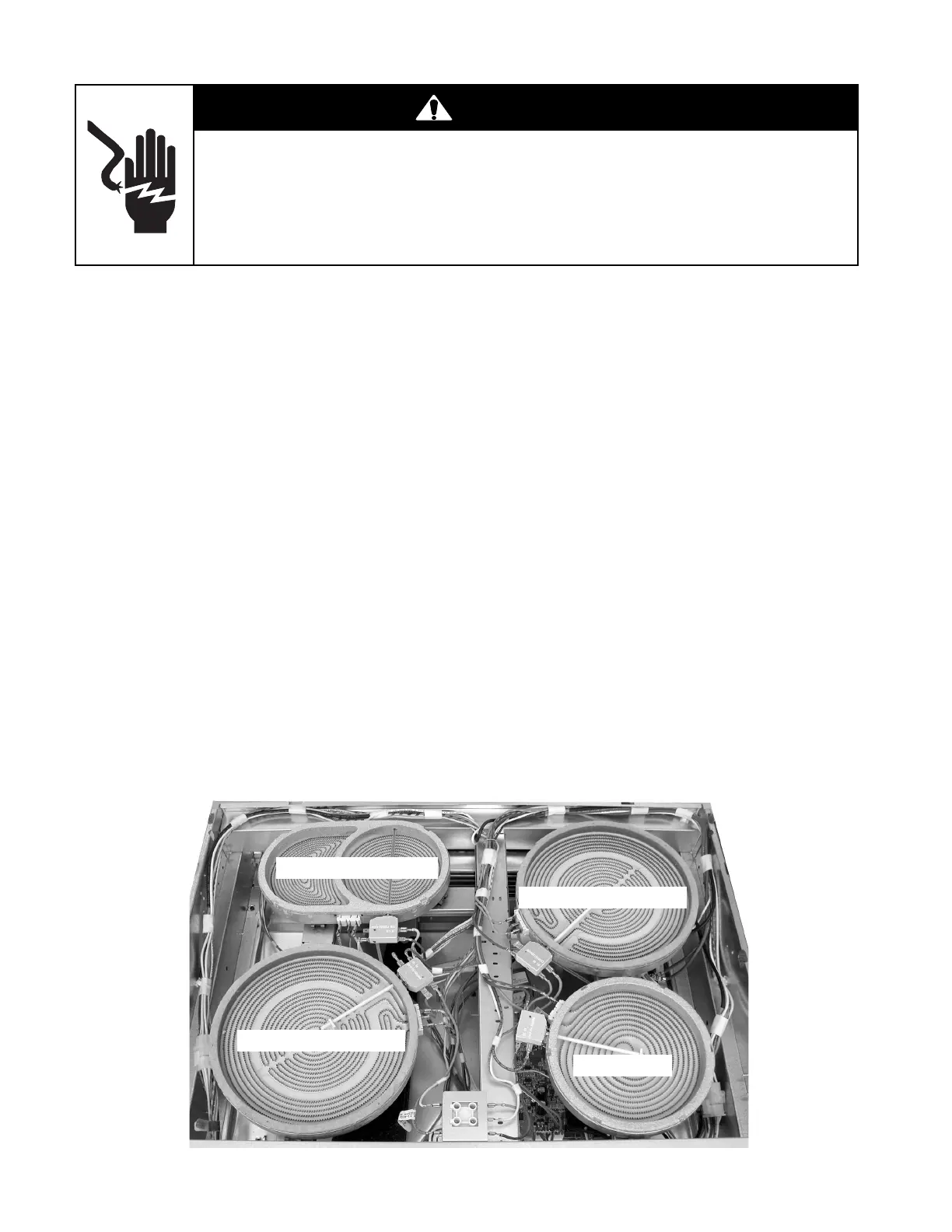
LR (YL-WH & YL-BK)
LF (OR-WH & OR-BK)
RR (BU-WH & BU-BK)
RF (BR-WH)
WARNING
Electrical Shock Hazard
Disconnect power before servicing.
Replace all parts and panels before operating.
Failure to do so can result in death or electrical shock.
• OR-WH and BK (BU-WH and BK)
= 52 to 64 Ω
LR (Dual Element)
• YL-WH and YL-BK = 120 to 130 Ω
• YL-BK and BK = 63 to 76 Ω
• YL-WH and BK = 52 to 64 Ω
RF (Single Element)
• BR-WH and element terminal
= 25 to 37 Ω