53 / 89 83000102.Ki
6.2.18. Electrical installation
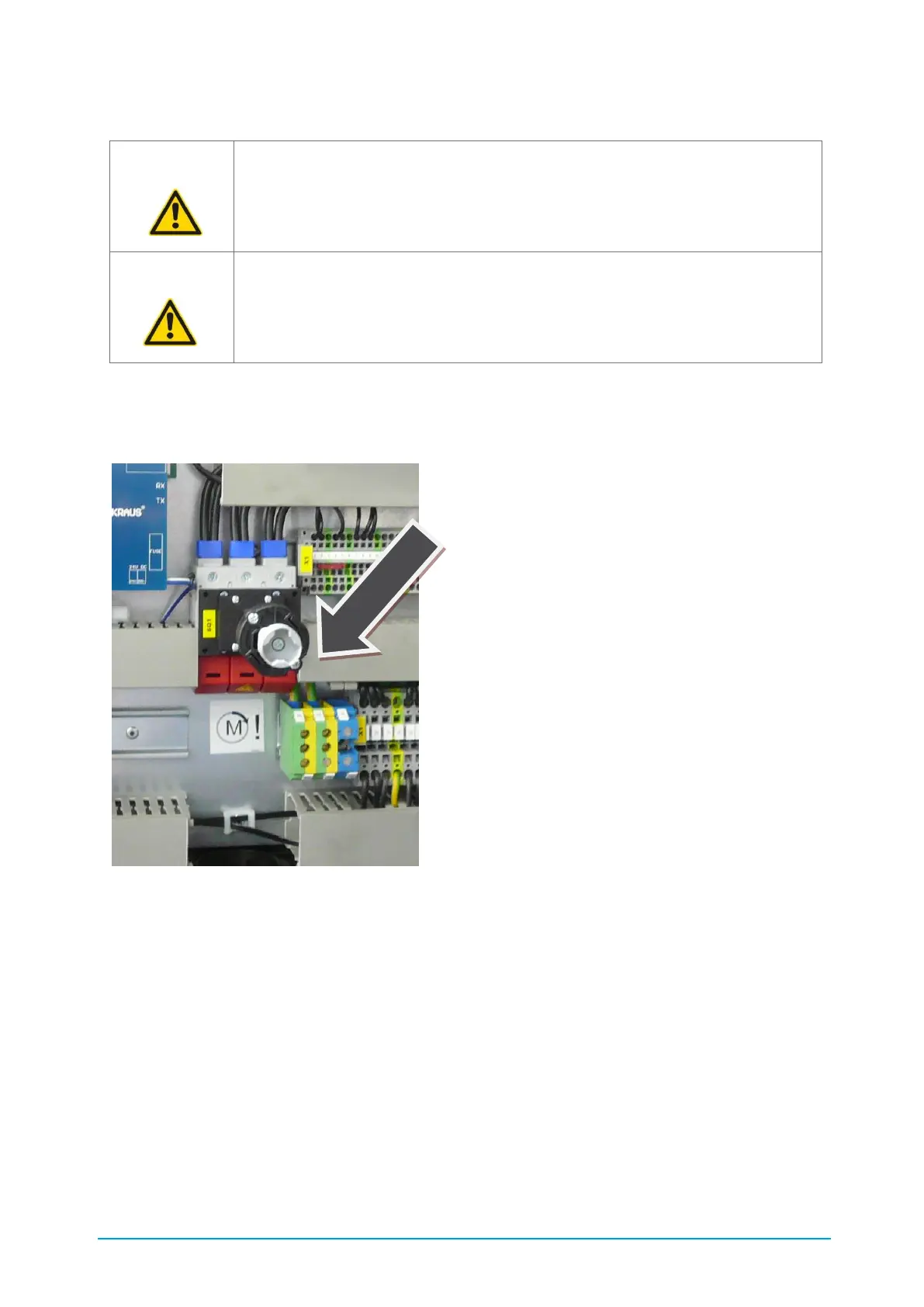
The chiller is connected electrically to its main supply terminal in the control cabinet. (see Figure
18 Main supply). A circuit diagram is supplied with the unit.
Figure 18: Main supply
The dimensioning of the load cable and the fusing must be in accordance with the machine's
technical data and the local regulations of the power supply company.
The supply cable must be routed into the machine. Cut-outs are provided for this purpose in the
baseplate and in the compressor mount (cBoxX 30 – cBoxX 100). Feed the supply cable,
protected by rubber grommets, through these openings (see Figure 18 Main supply).
Never switch on the chiller immediately if the machine is moved from a cold into a warm room.
The condensing moisture can damage electronic components. For the initial startup or following a
lengthy period out of use all the electronic components must have become acclimatised.
ATTENTION! The electrical installation, testing and commissioning may only be
carried out by qualified personnel. Note and follow the local regulations.
ATTENTION! Do not switch on the chiller until the hydraulic installation is
completed and the machine has been filled as specified in Chapter 6.2.15.
Otherwise the machine could be damaged.