60 / 89 83000102.Ki
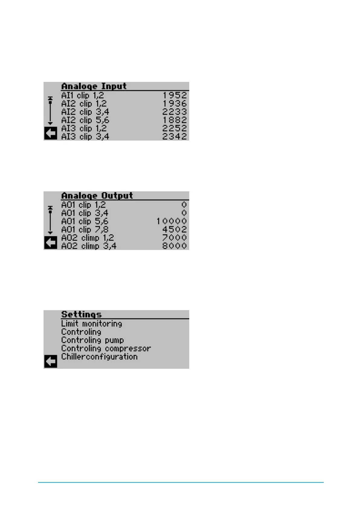
The analog inputs show the signal upstream of the analog digital converter. The value must be
between 0 and 4095. 0 means that no sensor is connected. 4095 means that the input is short-
circuited.
Figure 29: Analog inputs
The analog outputs show the signal upstream of the digital - analog converter. The value 10000
corresponds to an output voltage of 10 volts.
Figure 30: Analog outputs
8.5.4. Settings
All setpoint/target and parameter values and times are stored in the Settings menu.
Figure 31: Setting
8.5.5. Alarm menu
The alarm is acknowledged if the "OK" button is pressed for longer than eight seconds.(after five
seconds, the display switches back to the main menu)
• active: The alarm is still active. (e.g. DI MSS …) The motor protection switch has triggered.
• SH: The alarm is no longer queued. E.g. the motor protection switch has been unlocked on
the hardware side but has not yet been acknowledged at the control panel.