TP-6277 10/03 Installation 43
6.4.2 Antisiphon Device Installation
Install antisiphon devices when a fuel line section lies
below the highest point of the fuel tank. Install an
antisiphon device as follows:
D Use a spring-loaded check valve (tested to function
with the installation’s siphon head) or an electrically
operated shutoff valve (UL ignition-protected
tested to USCG regulations) that can operate
manually as the antisiphon device.
D Install the check valve above the fuel tank’s highest
point.
D Secure the check valve to the craft’s structure,
ensuring accessibility without removing permanent
structures.
D Locate the fuel-line section between the tank and
check valve above the fuel tank’s highest point.
Install an electric shutoff valve at the fuel tank’s
fuel-withdrawal fitting.
D Wire the shutoff valve to open whenever cranking
or running the generator set.
Antisiphon holes drilled into fuel dip tubes within the fuel
tank are unreliable antisiphon devices because they
become ineffective when restricted by dirt or gum.
6.4.3 Fuel Lines
Use a flexible hose section to connect the metallic line
from the tank to the engine fuel pump. USCG
regulations require that metallic lines have a wall
thickness of at least 0.74 mm (0.029 in.). Use seamless
annealed copper, copper/nickel, or copper tubing. The
flexible section allows vibrational motion of the
generator set during operation. Use USCG type-A
hose, marked and tagged according to regulations, for
the flexible section. Support the metallic line within
102 mm (4 in.) of its connection to the flexible section.
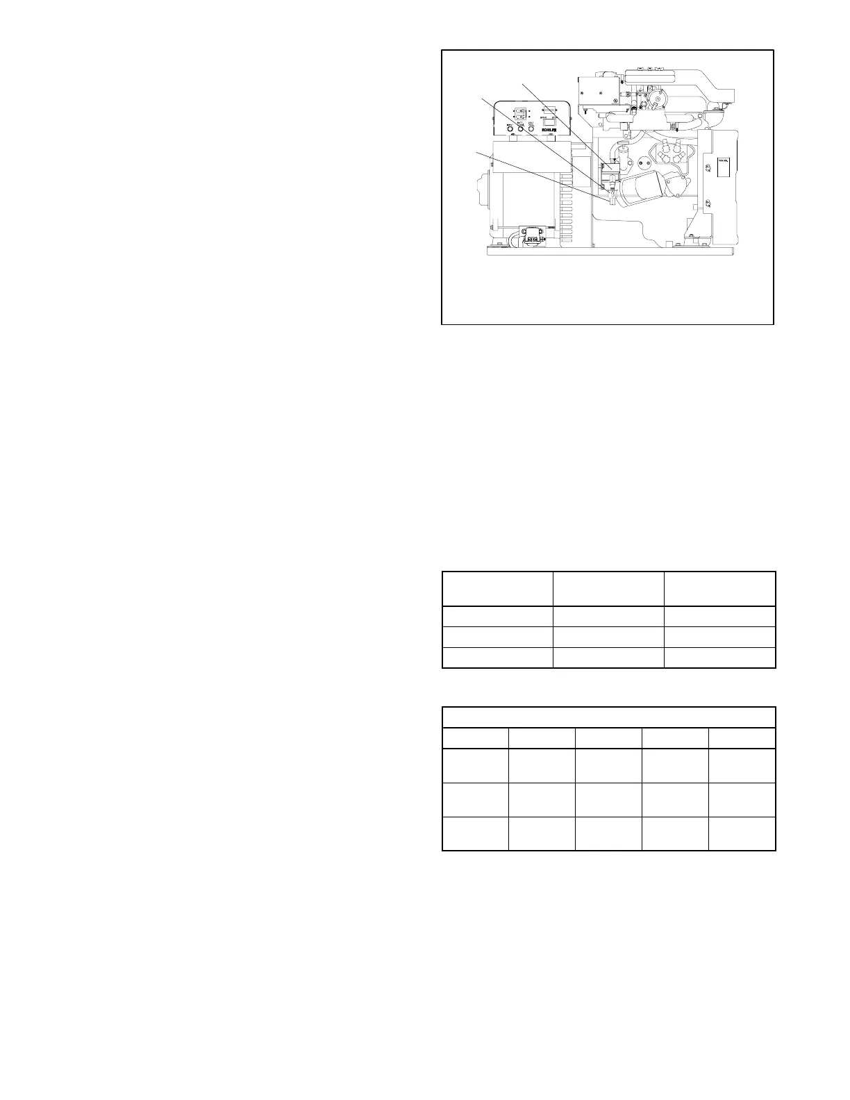
See Figure 6-5 for fuel inlet connection. Route the fuel
lines from the fuel tank in a gradual increase to the
engine. Do not exceed the height of the generator set
and do not run the fuel lines above the generator set.
1
3
1. 1/4 in. NPT female pipe thread
2. Fuel filter
3. Electric fuel pump
ADV-5661-C
2
Figure 6-5 Fuel Inlet Connection
6.4.4 Fuel Filters or Strainers
These generator sets are shipped with a fuel filter. No
additional fuel filter or strainer is required.
6.4.5 Fuel Pump Lift Capabilities and
Fuel Consumption
Figure 6-6 lists electric fuel pump lift capabilities and
fuel line sizes. Figure 6-7 shows generator set fuel
consumption rates.
Model
Fuel Pump Max.
Lift m (ft.)
Fuel Inlet Size
I.D. mm (in.)
8E 0.9 (3) 8 (5/16)
10E 0.9 (3) 8 (5/16)
12.5E 0.9 (3) 8 (5/16)
Figure 6-6 Fuel Pump Lift And Fuel Line Size
Load and L/hr. (GPH)
Model 1/4 1/2 3/4 Full
8E 2.2
(0.57)
2.8
(0.76)
3.6
(0.96)
4.4
(1.16)
10E 2.3
(0.61)
3.3
(0.86)
4.2
(1.10)
5.1
(1.36)
12.5E 2.80
(0.74)
4.09
(1.08)
5.50
(1.46)
6.60
(1.75)
Figure 6-7 Fuel Consumption