TP-6277 10/0348 Installation
Exhaust system guidelines for various generator set
locations follow. Information and illustrations of stern-
(rear) exhaust installations also apply to side-exhaust
installations. Where exhaust lines require passage
through bulkheads, use port- (left) or starboard- (right)
side exhaust outlets. This is especially true of
applications in which long exhaust lines to the transom
(rear) could cause excessive back pressure. See
Figure 6-17 for maximum allowable back pressures.
Should any information regarding installation conflict
with USCG regulations, follow USCG regulations.
Model
Allowable Exhaust
Back Pressure (Max.)
8/10/12.5E 6.7 kPa (2.0 in. Hg)
Figure 6-17 Allowable Exhaust Back Pressures
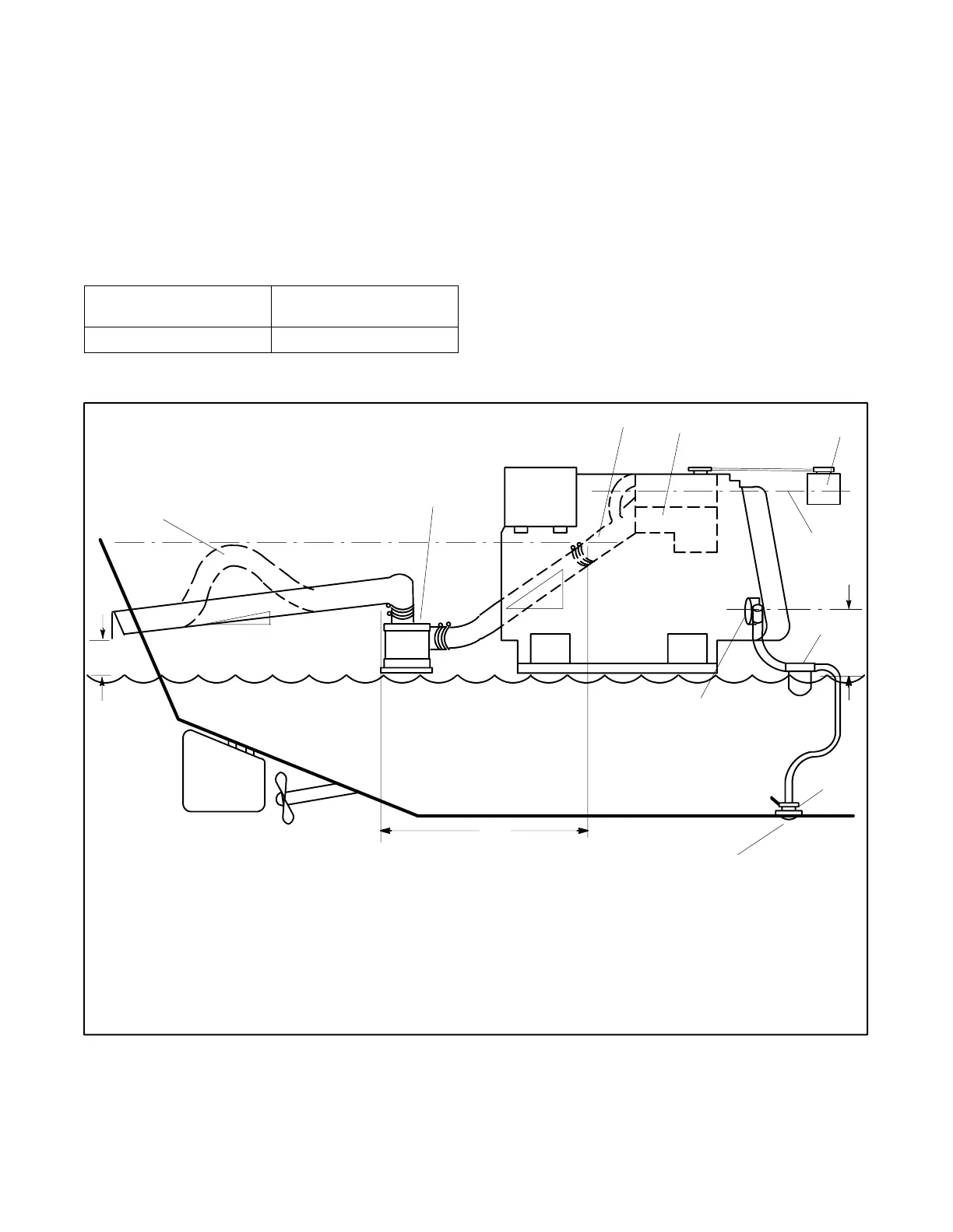
6.6.3 Above Waterline Installation
In addition to considerations described earlier, install a
customer-supplied silencer with the silencer’s outlet at a
maximum of 3 m (10 ft.) horizontally from the center of
the engine’s exhaust outlet. See Figure 6-18. Mount a
typical silencer with the inlet and outlet horizontal and
with drain plug down. Use a pitch of at least 13 mm per
30.5 cm (0.5 in. per running foot). Some silencers
require two supporting brackets or hanger straps for
installation to stringers or other suitable structures.
Locate any lift in the exhaust line, used to improve
silencing, below the engine exhaust manifold outlet.
Waterline
1
2
34
5
6
7
8
9
10
11
12
13
14
15
1. Slight lift improves silencing (keep below level of exhaust
manifold outlet) and prevents water backwash into silencer
2. Silencer (customer supplied)
3. Exhaust mixer elbow
4. Heat exchanger (locations vary by model)
5. Coolant recovery tank
6. Locate coolant recovery tank at same height as heat exchanger
7. Maximum seawater pump lift of 1 m (3 ft.)
8. Seawater strainer
9. Seacock
10. Intake strainer
11. Engine-driven seawater pump
12. Minimum exhaust hose pitch of 1.3 cm per 30.5 cm
(0.5 in. per ft.)
13. Maximum distance between silencer and exhaust mixer elbow
of 3 m (10 ft.)
14. Minimum exhaust hose pitch of 1.3 cm per 30.5 cm
(0.5 in. per ft.)
15. Minimum exhaust outlet distance above waterline of 10 cm
(4 in.)
NOTE: Data applies to both rear- and side-exhaust installations.
Figure 6-18 Typical Above Waterline Installation
Note: Use two hose clamps on each end of all flexible
exhaust connections.
Note: Read the text for a complete explanation of
dimensions and other installation considerations