TP-6277 10/03 Scheduled Maintenance 27
3.7 Distributorless Ignition System
(DIS)
The engine firing order is 1-2-4-3. The No. 1 cylinder is
located nearest to the front of the engine (pulley end).
The distributorless ignition system (DIS) consists of
several main components.
3.7.1 Crankshaft Position/Engine Speed
Sensor
The crankshaft position/engine speed sensor is on the
rear of the engine block and points toward the flywheel.
The sensor monitors the pattern of depressions on the
flywheel. One special longer depression corresponds to
90 degrees before top dead center (BTDC) on piston
number one. As the engine speed increases, so does
the frequency and amplitude of the variable reluctance
sensor voltage output signal.
3.7.2 Engine Coolant Temperature
Sensor
The engine coolant temperature sensor sends engine
temperature information to the universal electronic
spark control module. The sensor is in the intake
manifold water jacket.
3.7.3 Universal Electronic Spark
Control Module (UESC)
The universal electronic spark module receives the
alternating signals from the engine coolant temperature
sensor and uses the information, along with engine load
and temperature, to determine the optimum ignition
advance for all engine operating conditions. The
module then interrupts the primary voltage to the DIS
coils, releasing the ignition spark at the optimum
moment.
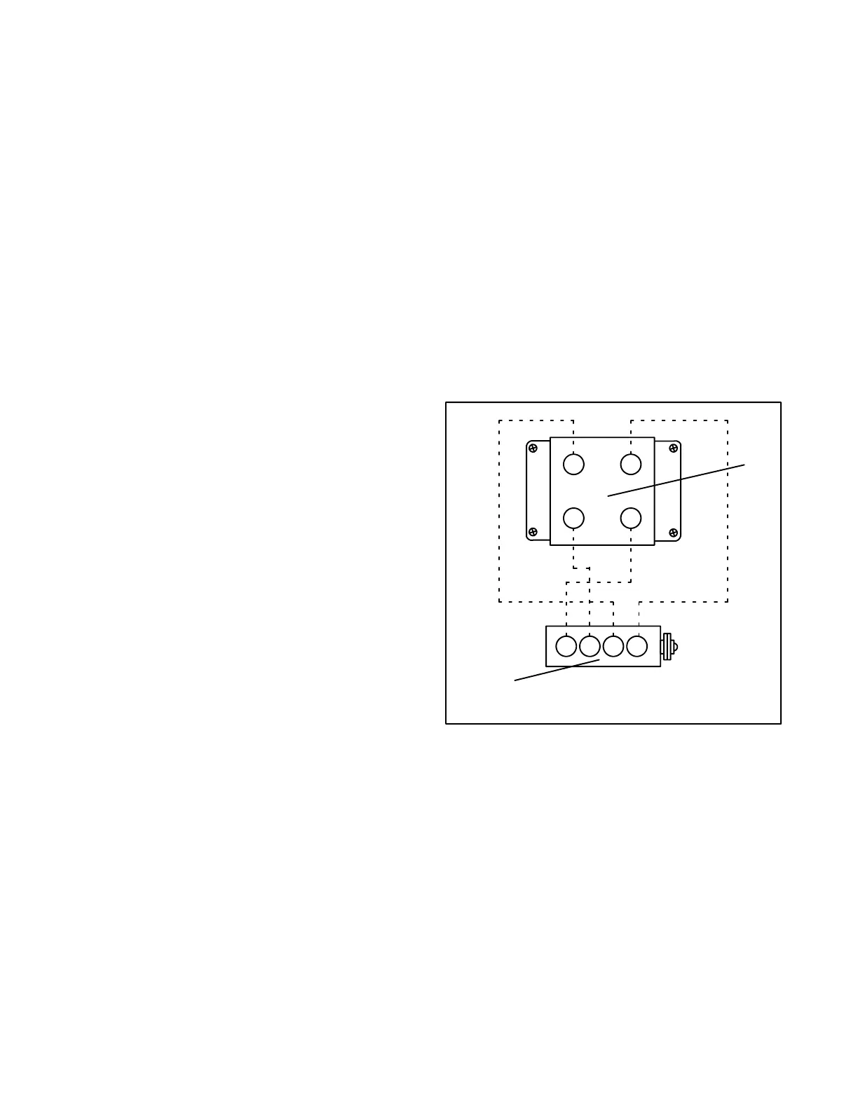
3.7.4 DIS Coil Assembly
Internally, the DIS coils have two primary windings and
two high-voltage secondary windings. One secondary
coil supplies high tension voltage to cylinders 1 and 4.
The secondary coil supplies cylinders 2 and 3 via high
tension leads and spark plugs. See Figure 3-20. When
either of the two secondary coils is energized, two
sparks are released, one going to a cylinder on the
compression stroke and the other to a cylinder on the
exhaust stroke (e.g. cylinder no. 1 and cylinder no. 4
respectively). The unused spark has no detrimental
effect.
The ignition circuit effectively becomes a
maintenance-free item. Only the spark plugs require
inspection and replacement at the specified service
intervals.
Fuel octane rating fixes the ignition timing.
1
4
2
3
1234
1
2
1. DIS coil assembly
2. Cylinder block
TP-5399-3
Figure 3-20 DIS Coil Terminal Identification