TP-6277 10/03 Installation 45
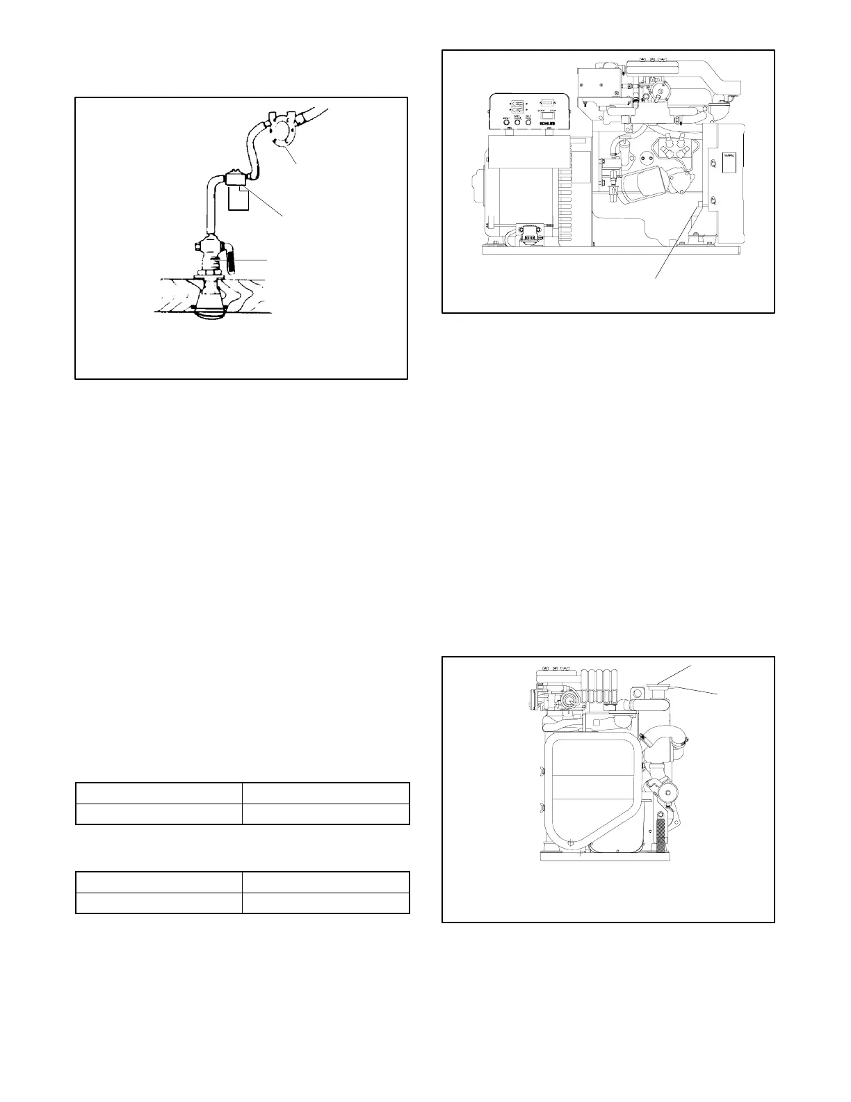
Note: Some seawater strainers include a seacock and
an intake through-hull strainer.
1
2
3
1-789
1. Seawater pump
2. Seawater strainer
3. Seacock
Figure 6-10 Seawater Strainer
6.5.4 Waterlines
Waterlines from the seacock to the engine-driven
seawater pump are usually constructed of flexible hose
or copper tubing. Use a flexible section of hose for
connection to the seawater pump to allow for vibrational
motion of the generator set during operation. The hose
should have an inside diameter of 19 mm (3/4 in.).
Support a nonflexible waterline within 102 mm (4 in.) of
its connection to the flexible section.
Keep the seawater hose as straight and short as
possible. If the hose is too long, usually over 4.6 m
(15 ft.), water draw problems may occur. Avoid running
the inlet pipe above the generator. See Figure 6-11 for
correct identification of water line hose sizes. See
Figure 6-12 for the maximum seawater pump lift. See
Figure 6-13. for the seawater connection to the
seawater pump inlet. The seawater outlet combines
with engine exhaust gases.
Model WaterLineHoseI.D.
8/10/12.5E 16 mm (5/8 in.)
Figure 6-11 WaterLineHoseI.D.
Model Seawater Pump Lift (Max.)
8/10/12.5E 0.9 m (3 ft.)
Figure 6-12 Seawater Pump Lift (Maximum)
1
1. Seawater pump inlet
ADV-5661-C
Figure 6-13 Seawater Pump Inlet
6.5.5 Closed/Heat Exchanger
Closed heat exchanger cooling is the best alternative for
most applications. See Figure 6-15. Provide service
accessibility for the heat exchanger pressure cap.
If using a coolant recovery tank, install it on the engine or
engine stringer. Mount the coolant recovery tank so its
surface level is the same height or 5 cm (2 in.) max.
below the level of the pressure cap. See Figure 6-15 for
a typical installation. See Figure 6-14 for coolant
recovery tank connections.
Note: If a coolant recovery tank is not used, be sure that
the overflow hose is not immersed in the bilge
water to prevent bilge water from being siphoned
back into the cooling system.
1
2
ADV--5661
Note: Use supplied hose to connect
to coolant recovery tank.
1. Cooling system pressure cap
2. Overflow tube
Figure 6-14 Coolant Recovery Tank Connections