21
7. How to Set a Probe
1
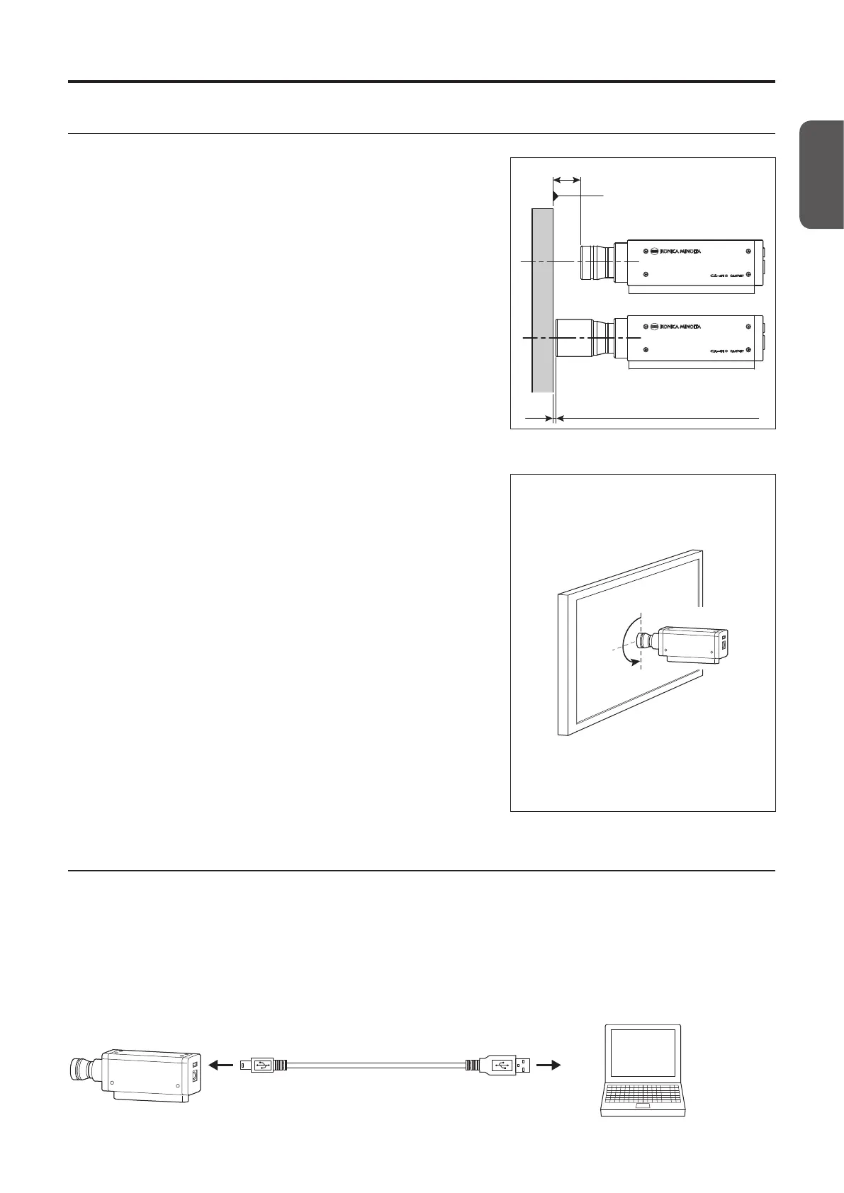
Secure the display.
L = 30 mm
*1
2 mm (1 mm for mini probes)
Display surface of the display
(when a light-shielding cylinder is not used)
(when a light-shielding cylinder is used)
2
Secure the probe in a way to place its end 30 mm *
1
away from the display surface.
Be sure to set it perpendicular to the display.
*1: L = 10 mm for mini probes.
Notes on setting
• When measuring displays with high view angle dependence, you can
obtain a higher measurement reproducibility by not changing the
setting angle θ for every measurement. In particular, the CA-VP410
high-sensitivity probe has a large aperture angle, which has a greater
eect on the viewing angle. When measuring displays with a high view
angle dependence, run user calibration and use the probe without
rotating it from the calibrated position.
• Use of the light-shielding cylinder supplied as a standard accessory not
only blocks ambient light but also makes it easier to achieve a proper
measurement distance and an angle of 90°.
•
For a 27 probe, the specification range of the length is 30 mm±10 mm.
•
For a 10 probe, the specification range of the length is 30 mm ±5 mm.
•
For a mini probe, the specification range of the length is 10 mm ±5 mm.
•
When strict low-luminance measurement is required, perform
measurement in a dark room with no external light. Even when measuring
in a dark room, the ambient light from the display itself may act as an
external light. In such situations, light shielding using a light-shielding
cylinder is recommended. If strict limitations are required, compare
measurement results from a general luminance meter such as the
CS-2000, and verify whether using a light-shielding cylinder has any eect.
Setting angle θ
Probe
Display
8. How to Connect Cables
A probe has a USB connector for connecting a USB mini B plug and a connector for connecting an RS-232C mini DIN plug.
Before connection, make sure that power is not supplied to the probe and the external device. Be sure to connect a cable
plug to the specified connector.
• For USB connection with a PC, connect the USB mini B plug of the supplied USB cable IF-A28 to the USB connector of the
probe. Connect the USB plug on the other side of the cable to the USB connector of the PC.
USB connection (using IF-A28)
Mini B plug
IF-A28
USB plug
PC
Probe Guide