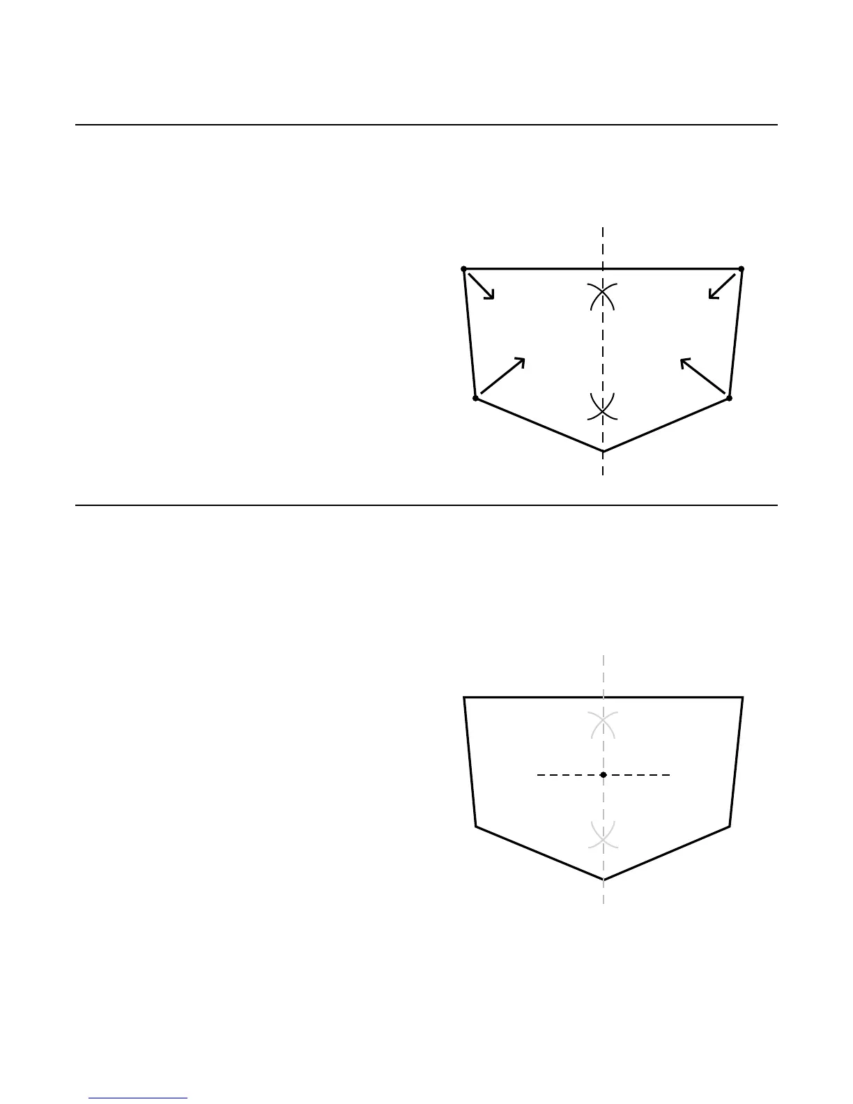
1.1 Scribe an arc from points A and B to the bottom center of
the transom exterior. Scribe an arc from points C and D to
the top center of the transom exterior. Where the previous
mentioned arcs intersect, scribe a vertical line approxi-
mately 28 in. (71 cm) long. This will represent the center
line of the stern drive.
NOTE: For twin application, measure (to
the port and starboard) off the vessel verti-
cal center line over to the engine crank shaft
center line and scribe a vertical center line
parallel to the vessel vertical center line. See
the lower drawing of Figure B on page 10 in
this manual for explanation.
1.2 After establishing the x-dimension (see Figure B on page
10 in this manual), scribe a horizontal line at least 18 in.
(46 cm) long, perpendicular and centered on the existing
vertical line (scribed in Step 1.1).
NOTE: Specic characteristics of an installation may
change the recommended vertical drive position. Please
contact Konrad with any specic concerns.
ATTENTION: If you are installing the Konrad
“Rear Mount / Tail Piece” assembly, please go
to step 19 (page 73 - 74) in this manual.
Step 1: Transom Cutout
FIGURE 1B
FIGURE 1A
500 SERIES INSTALLATION MANUALJANUARY 2010 PAGE 11