500 SERIES INSTALLATION MANUALJULY 2016 PAGE 27
FIGURE 5I
FIGURE 5J
5.7 Slide drive onto transom assembly. The splined end yoke
shaft and u-joint assembly must be held up and guided
into the gimbal carrier or tailpiece assembly.
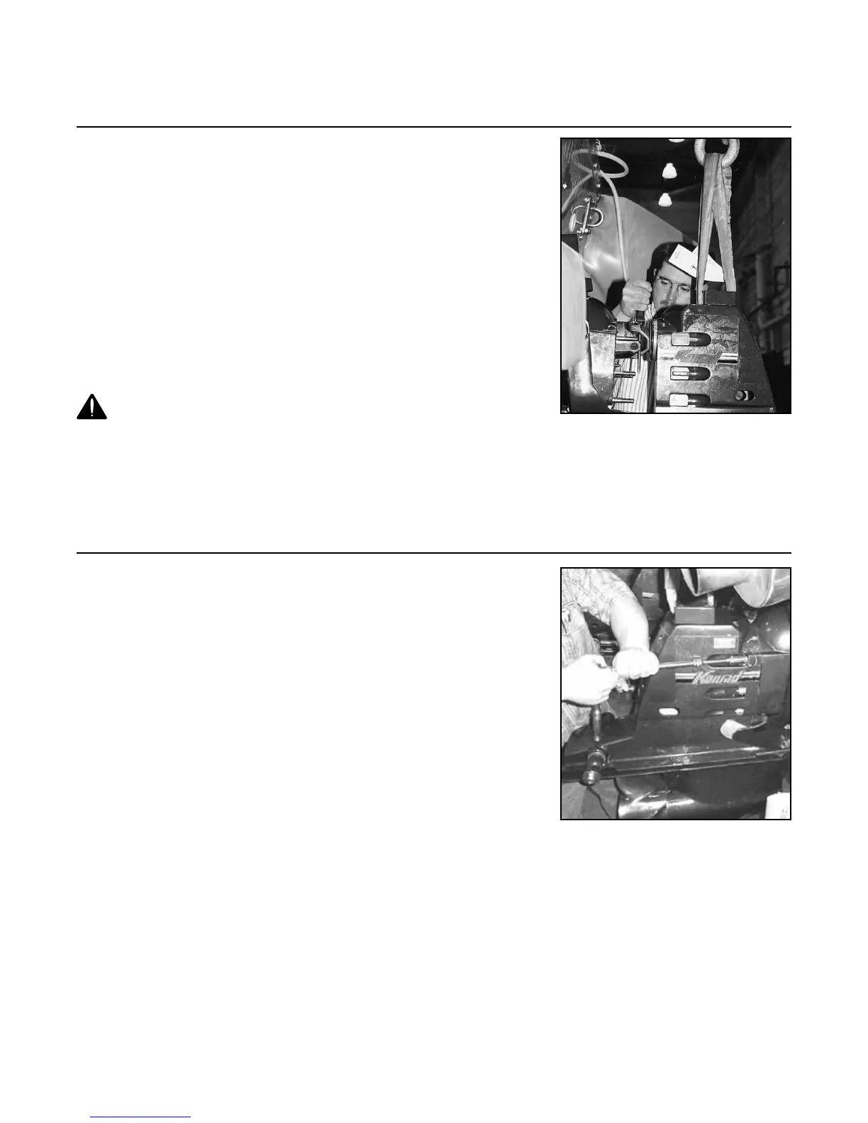
NOTE: It may be necessary to rotate the splined end
yoke shaft (this can be achieved by sliding the propeller
onto the splined propeller shaft and rotating it back and
forth or re-orientating input yoke using a screwdriver as
pictured in Figure 5I) or yoke assembly so the splines
line up for the drive to be fully seated against the transom
assembly.
NOTE: If the stern drive does not engage easily, pull
stern drive back, reset engagement pin and reattempt 5.7.
WARNING! Do not impact or apply force to the drive
while engaging the input shaft as this will damage the
gimbal carrier seal.
5.8 Fasten the stern drive to the transom assembly using the
six (6) nuts and six (6) washers provided. Torque to 55 lb.
ft. (74 Nm).
NOTE: Be sure to put the continuity cable ring on the
upper starboard stud before putting the washer and nut
on.
An alternate method of stern drive installation is to remove
the gimbal carrier assembly (non-tailpiece applications)
from the gimbal housing (inside of the vessel). This can be
done by removing the three (3) S.H.C.S. (10-385). Hold
up the splined end yoke shaft and guide it into gimbal
carrier as the carrier is reinstalled. Torque the three (3)
S.H.C.S. (10-385) to 70 lb. ft. (95 Nm).
Step 5: Stern Drive Installation (continued)