500 SERIES INSTALLATION MANUALJULY 2016 PAGE 17
3.6 For tailpiece application, a gimbal carrier is not utilized.
Connect oil bottle to long 1/4 in. hose. Connect 3/8 in.
hose which is attached to the gimbal housing to brass
reducer coupling, located on 1/4 in. hose.
3.7 Fill oil bottle to “ll” line with Konrad 75W90 synthetic
gear lube.
NOTE: In accordance with MSDS regulations and
requirements, the stern drive is shipped full of the above
mentioned lubricant. Prior to operation, verify that the
entire system is completely purged of air and lled with
lubricant. If a different gear oil is chosen for your
application, it is recommending that the stern drive is
drained and relled. This may void manufacturer’s
warranty. Purge oil line to the stern drive by manually
opening connecting valve located on the outside port face
of bell housing (outboard side of transom). Open valve
until solid oil ow occurs. Rell oil bottle at proper level
indicated on bottle.
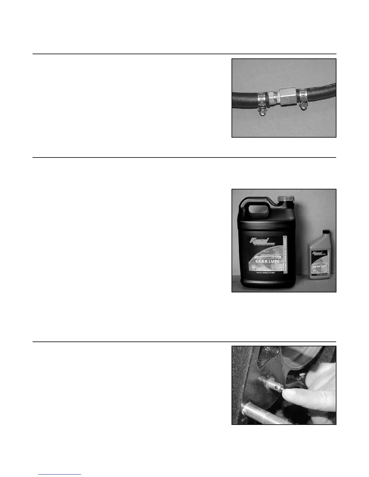
3.8 Purge the air out of the oil line feeding the stern drive
by depressing the check valve nipple, located on the bell
housing face, until a solid stream of oil comes out. Rell
reservoir bottle to the appropriate level.
FIGURE 3G
FIGURE 3H
Step 3: Oil Reservoir Installation (continued)
FIGURE 3I