500 SERIES INSTALLATION MANUAL JULY 2016PAGE 14
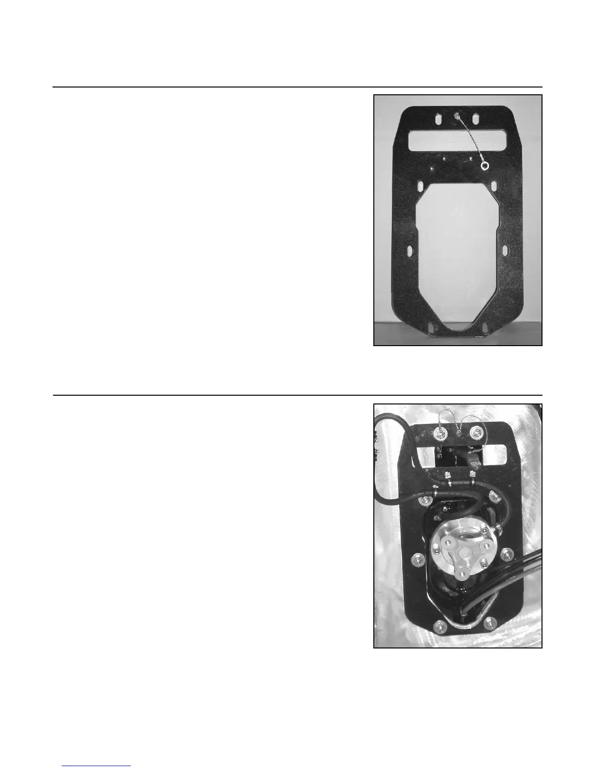
2.3 Place the inner transom backing plate (10-357) over the
eight (8) studs from the inside of the vessel.
NOTE: If an internal steering cylinder is going to be
used, the bracket can be mounted on the upper one (1) or
two (2) sets of horizontal studs depending on the steering
cylinder style used.
NOTE: The inner transom plate may require modication
or elimination depending on steering cylinder assembly
used.
NOTE: If an inner transom backing plate is not used, the
round washers (10-415) must be replaced with rectangular
washers (10-941).
2.4 Secure the transom assembly to the transom by using
eight (8) nylock nuts (10-334) and eight (8) at washers
(10-415). Torque to 25-30 lb. ft. (34-41 Nm).
NOTE: Place inner transom backing plate continuity
cable between the washer and nylock nut of either of
the top two transom assembly studs before tightening (if
applicable).
NOTE: Connect the tiller arm continuity cable to the
inner transom backing plate by using the small phillips
head screw (if applicable).
NOTE: The two (2) oil lines in this photo will be ran and
attached in a later step.
Step 2: Transom Assembly Installation (continued)
FIGURE 2D
FIGURE 2E