500 SERIES INSTALLATION MANUAL JULY 2016PAGE 18
Wire style and gauge shall meet requirements of local, state and
national codes.
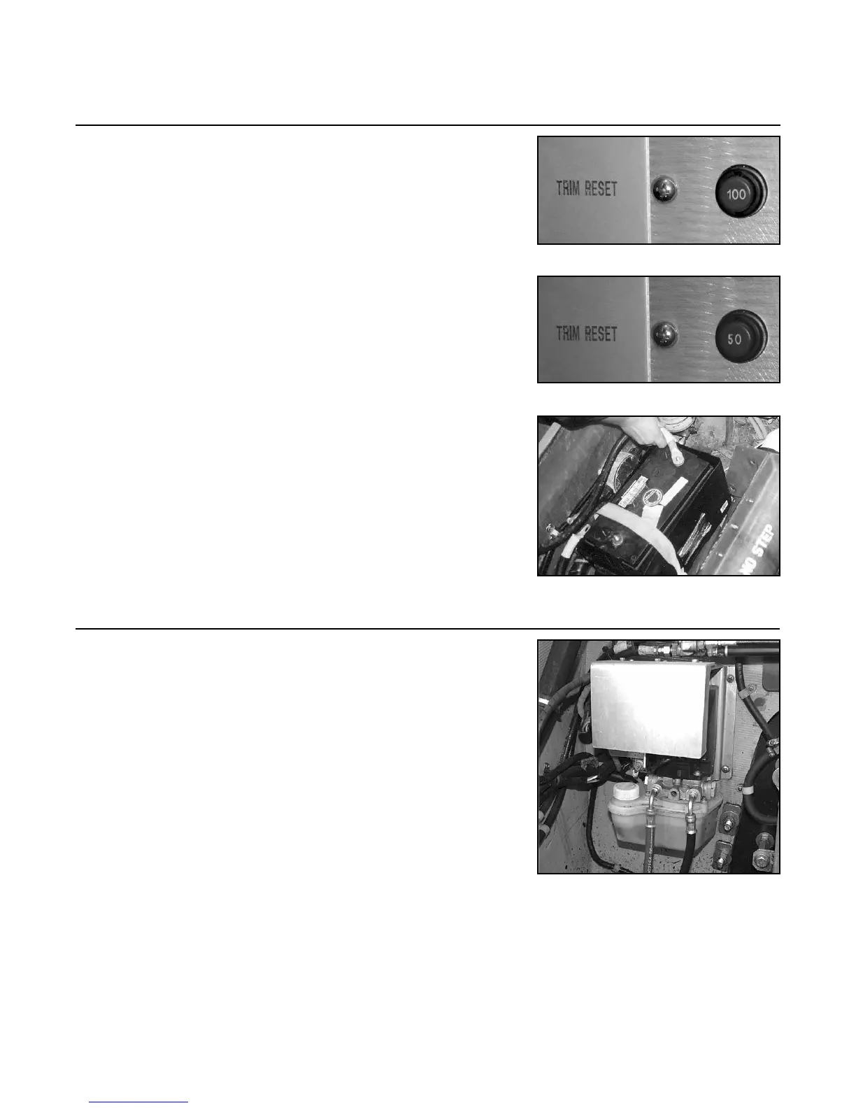
4.1 Trim pump circuit requires inline fuse/breaker (on the
positive lead) of the following values:
1) 12 Volt = 100 Amperes (see Figure 4A)
2) 24 Volt = 50 Amperes (see Figure 4B)
This item should be mounted in an accessible and logical
position away from bilge uid contact. It must also be
labeled clearly.
NOTE: Battery, or batteries, must be disconnected while
all electrical connections are being made or serviced (see
Figure 4C).
NOTE: Refer to the Trim System Electrical Drawings
(Figure C and Figure D on pages 22 and 23 in this
manual) for further documentation on this and proceeding
instructions.
4.2 Mount trim pump in a location which is:
1) As elevated as possible and away from bilge
uid contact.
2) Is within reach of transom assembly wiring
approximately 36 in. (91.4 cm).
3) Is within reach of oil bottle wiring
approximately 48 in. (122 cm).
4) Is within reach of transom assembly hydraulic
hoses, 32 in. or 48 in. (81.3 cm or 122 cm).
Measure to determine length.
NOTE: For berglass hulls, it is recommended that a
pilot hole be drilled prior to lag screw installation.
NOTE: For metal hulls, attach by either welding or us-
ing a mounting plate.
NOTE: The two (2) hydraulic hoses in this photo will be
attached in later steps.
Step 4: Trim/Lift Pump Installation
FIGURE 4A
FIGURE 4D
FIGURE 4B
FIGURE 4C