500 SERIES INSTALLATION MANUALJULY 2016 PAGE 37
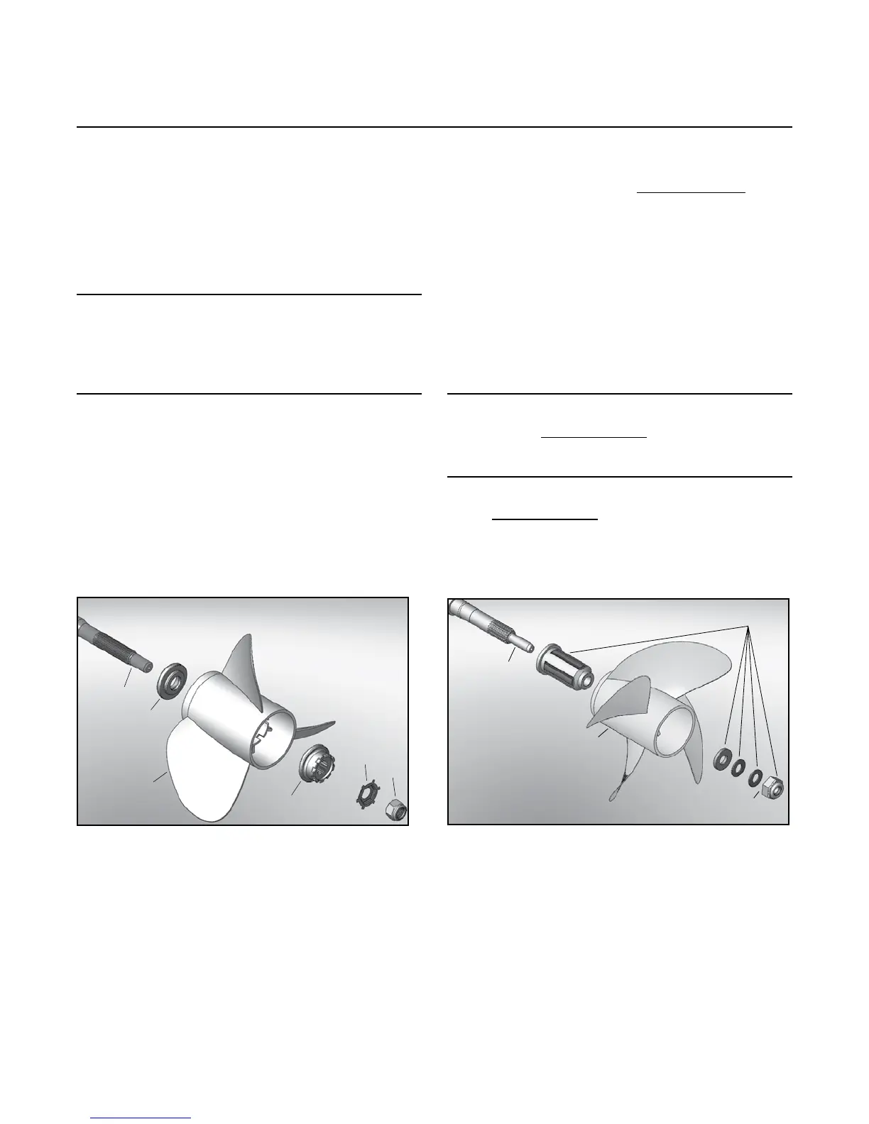
Step 8(a): 520 & 540 Propeller Installation
Description Qty Part #
A ............ Prop shaft (L) OR ...........1.........10-677
Prop shaft (R) .................1.........10-596
B ............ Propeller .........................1........ variable
C ............ Prop hardware kit ...........1.........10-680
D ............ Propeller nut ................. 1/0 .......10-667
Description Qty Part #
A ............ Prop shaft (L) OR .......... 1 ......... 10-360
Prop shaft (R) ................. 1 ......... 10-363
B ............ Forward thrust hub ......... 1 ......... 10-292
C ............ Propeller ......................... 1 ........ variable
D ............Splined washer ............... 1 ......... 10-293
E ............Tab washer ..................... 1 ......... 10-295
F ............Propeller nut .................. 1 ......... 10-296
Model 540
A
B
C
D
E
F
A
B
C
D
Model 520
8.1a Grease and slide thrust washer onto propeller
shaft (model 520 only).
NOTE: Tapered end of thrust washer must
be towards the drive.
8.2a Grease splined area and the threads of the
propeller shaft.
8.3a Place the propeller on the propeller shaft
followed by the appropriate hardware (see
below).
8.4a Torque the propeller nut to 80 lb. ft. (109
Nm) for the 520 model. When approaching
80 lb. ft. (109 Nm), 520 model only, make
sure that the tabs on the tabbed retaining
washer (at least 2 out of 6) line up with the
grooves in the splined washer/hub.
NOTE: A block of wood can be placed
between the propeller and the lower drive
housing to prevent the propeller from
spinning, while torquing the propeller nut.
8.5a Torque the propeller nut to 55 lb. ft. (75 Nm)
for the 540 model only.
8.6a Bend over the tabs using appropriate tools,
520 model only.