500 SERIES INSTALLATION MANUAL JULY 2016PAGE 12
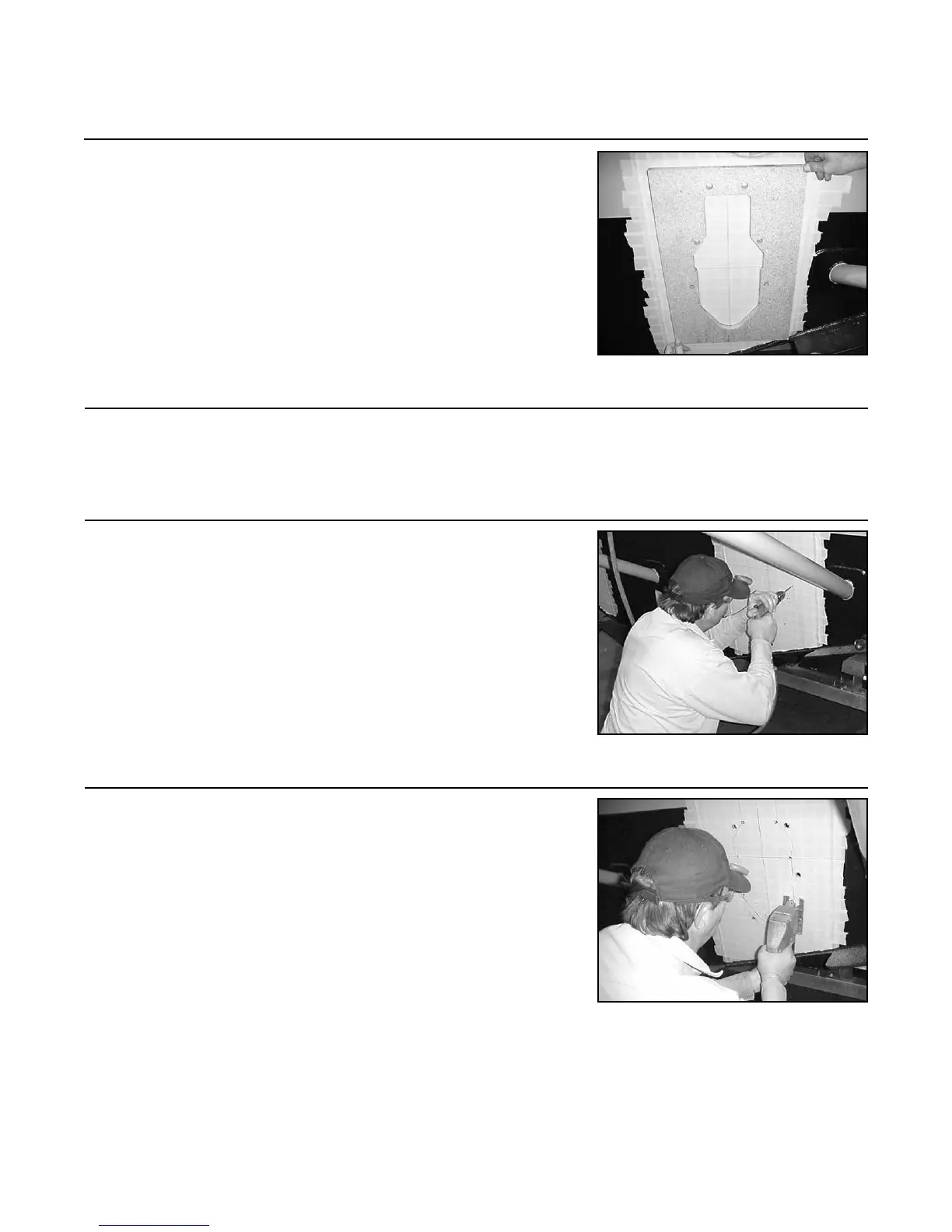
1.3 Place the cutout template (10-455) on the exterior of the
transom and position it so the scribed horizontal and ver-
tical match up with the scribed center lines on the tem-
plate.
1.4 Trace the cut out area and the eight (8) holes. Remove the
template.
1.5 Center punch the eight (8) holes traced in Step 1.4. Drill
the eight (8) holes through the transom using a 5/8 in. (16
mm) drill bit.
NOTE: Holes must be drilled perpendicular to the tran-
som face.
1.6 Using a reciprocating saw, cut out the area traced in Step
1.4. Use a le or rasp to touch up the cutout area.
NOTE: Cut must be made perpendicular to transom
face.
NOTE: For berglass transoms, it is recommended that
berglass epoxy resin be applied to the cut areas. Verify
that cutout area is correctly sized and shaped before
applying epoxy. Allow proper drying/setup time for epoxy
to cure.
Step 1: Transom Cutout (continued)
FIGURE 1A
FIGURE 1C
FIGURE 1B