500 SERIES INSTALLATION MANUALJULY 2016 PAGE 49
FIGURE 12C
FIGURE 12D
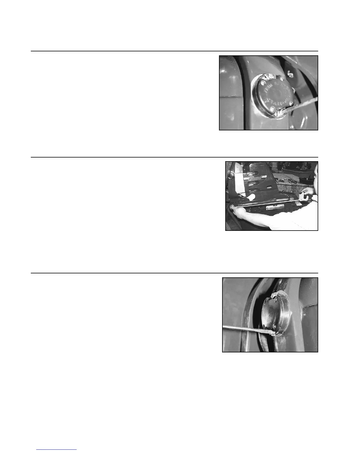
12.2 Loosen the starboard side switch on the transom assembly
and rotate the switch until gauge reads DN (farthest down
position).
NOTE: If this position cannot be achieved by rotating
the switch, it will be necessary to take the switch com-
pletely off the transom assembly and rotate the gray star-
hex shaped knob until desired position is achieved. Re-
mount the switch and ne tune.
12.3 Set the drive at approximately eight degrees (+8°). This
can be accomplished by trimming the drive up until the
trim cylinder measures 22 in. (56 cm) between the center
of the front anchor pin and the center of the rear anchor
pin.
NOTE: Alternate method of setting the drive at eight
degrees (+8°): Insert a 1 in.(2.54 cm) shim at the front of
the top cover. Place one end of a level on the 1 in. (2.54 cm)
shim and the other end on the back of the top cover. Trim
the drive up or down until the level indicates levelness.
12.4 Loosen the port side switch on the transom assembly and
rotate until the red and green LED’s are on the verge of
switching.
NOTE: If this position cannot be achieved by rotating
the switch, it will be necessary to take the switch off the
transom and rotate the gray star-hex shaped knob until
desired position is achieved. Remount the switch and ne
tune.
Step 12: Setting Trim/Lift Limit & Sender Switch (continued)
FIGURE 12E