500 SERIES INSTALLATION MANUAL JULY 2016PAGE 48
NOTE: If mechanical trim indicators are used, skip
Step 12 and refer to the manufacturers instructions for
installation and adjustment.
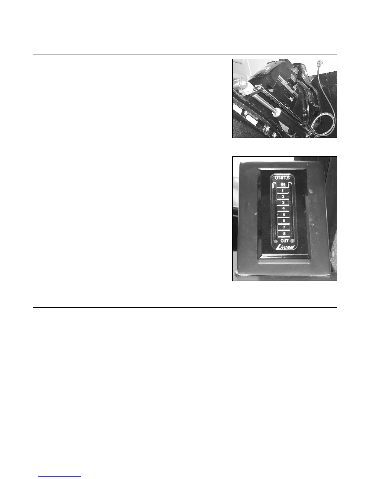
12.1 Trim the drive all the way to the down position, approxi-
mately negative seven degrees (-7º).
NOTE: In the case where trim limiting trim cylinders
are used, trim the drive all the way to the down position,
approximately negative two degrees (-2º).
Step 12: Setting Trim/Lift Limit & Sender Switch
FIGURE 12A
FIGURE 12B