500 SERIES INSTALLATION MANUAL JULY 2016PAGE 28
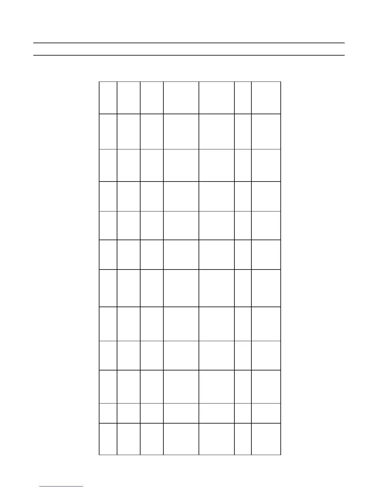
Alignment Specifications Chart for Transmission to Stern Drive Coupling
Coupling
Type
Part # Length
(Range)
Parallelism Concentricity Axial Slip
Compensation
Coupling
Orientation
Tools
Suggested
Torque
(Fasteners)
Thread Lock
Compound
Transmission
Type
Stern Drive
Carrier Type
Direct
30-449
Fixed
(Close
Couple)
N/A N/A Fixed N/A TO-094 N/A N/A
Tail Piece
Coaxial
N/A
Direct
30-286
30-287
30-464
Fixed
(Close
Couple)
< .003 in.
< .076 mm
< .003 in.
< .076 mm
N/A
Yes
(See
Step 15)
11-284
GO-017
70 ft. lbs.
95 Nm
Yes
Output
Flange
3-Lobe
30-301
Driveshaft
w/Rubber
Couplings
Short
30-264
9 - 15 in.
23 - 38 cm
< .010 in.
< .254 mm
< .010 in.
< .254 mm
1 in.
25.4 mm
Yes
(See
Step 15)
GO-017
TO-096
70 ft. lbs.
95 Nm
Yes
Output
Flange
3-Lobe
30-301
Driveshaft
w/Rubber
Couplings
Long
30-272
15 - 48 in.
38 - 122 cm
< .010 in.
< .254 mm
< .010 in.
< .254 mm
1 in.
25.4 mm
Yes
(See
Step 15)
11-284
GO-017
70 ft. lbs.
95 Nm
Yes
Output
Flange
3-Lobe
30-301
11-797
30-391
>9.5 - <55 in.
25.4 - 140 cm
Max 2° Max Offset 2°
1/16 in.
1.59 mm
N/A GO-017
85 ft. lbs.
115 Nm
Yes
Output
Flange
30-303
U-Joint
Carden
30-043
>9.5 - <60 in.
24 - 152 cm
< .010 in.
< .254 mm
Compound
Offset
between
.5°< x <1°
1 in.
25.4 mm
Yoke
Orientation
GO-017
89 ft. lbs.
121 Nm
Yes
Output
Flange
30-303
*
In most cases, the use of a u-joint shaft is not recommended, please contact Konrad for approval prior to installation.
FIGURE E: ALIGNMENT SPECIFICATIONS CHART