500 SERIES INSTALLATION MANUAL JULY 2016PAGE 32
Step 6: Alignment Procedures (continued)
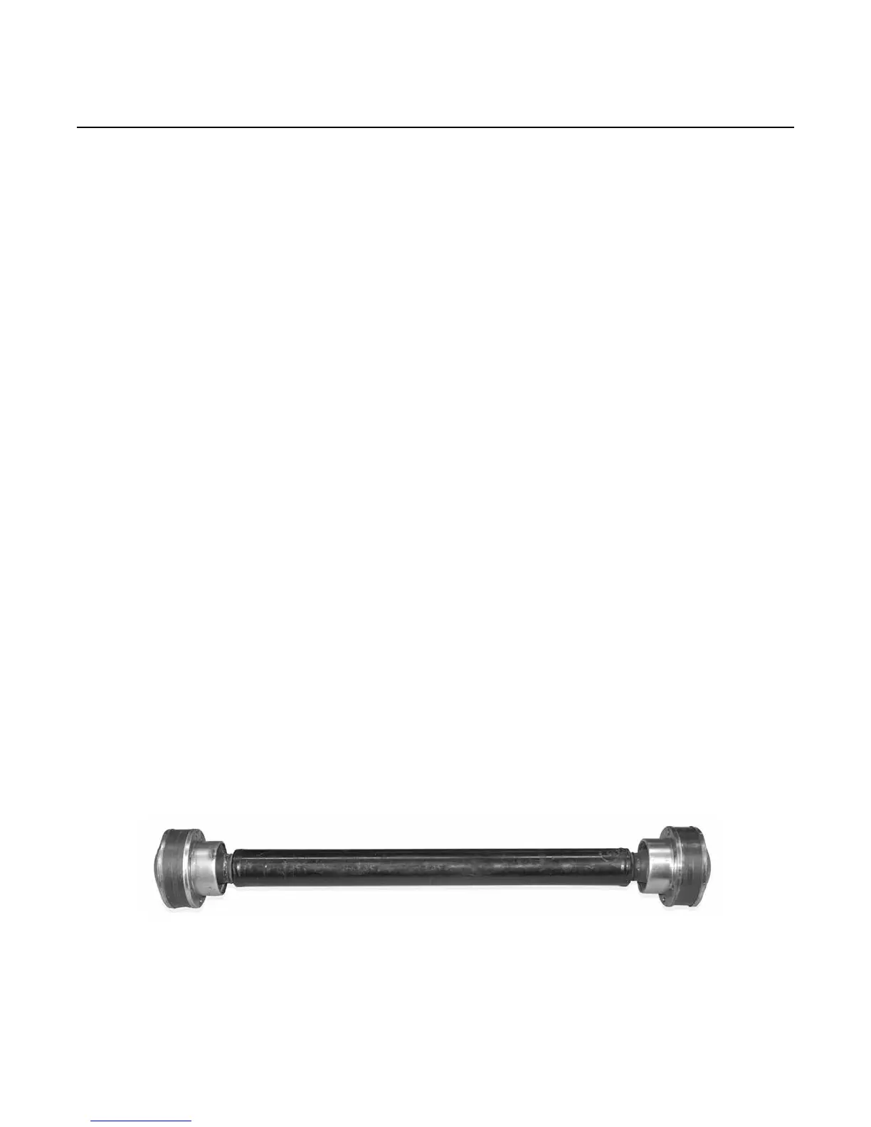
E) CV Extension Shaft
NOTE: The transmission output ange and gimbal
carrier input ange must be parallel within two de-
grees (2°) or manufacturer’s approval dependent on
power and RPM levels.
1) A constant velocity joint is recommended over
a u-joint shaft because, unlike the u-joint, it has
no signicant impacts on the stern drive gear
sets.
2) The transmission output ange and gimbal car-
rier input ange must be concentric within
the manufacturer’s recommended specications.
3) Fix magnetic base, arm and dial indicator
assembly (GO-017) to transmission output
ange.
4) Rotate transmission ange indicating the face
of the alignment ange. All facial measure-
ments must be within manufacturer’s require-
ments.
5) Rotate transmission ange indicating the
circumference of the alignment ange. All
measurements must be within the manufac-
turer’s requirements.
6) Refer to Step 17 on pages 70 - 71 in this manual
for CV extension shaft installation.
7) The axial distance must be within .0625 in.
(1.59 mm) of the shaft’s working length
(including the adapter anges).
FIGURE 6E