500 SERIES INSTALLATION MANUALJULY 2016 PAGE 31
Step 6: Alignment Procedures (continued)
D) U-Joint Extension Shaft
NOTE: It is recommended to hold either the horizontal or
vertical offset at zero and achieve the offset in one plane.
In most cases it is easier to hold the horizontal measure-
ment at zero. In most cases, the use of a u-joint shaft is not
recommended, please contact Konrad for approval prior to
installation.
1) Transmission output ange and gimbal carrier
input ange must be parallel within .010 in.
(.25 mm).
2) Transmission output ange and gimbal carrier
input ange must have a compounded vertical
and horizontal offset angle (a) which is
1.0˚ > (a) > 0.5˚. This dimension is a function
of the length of the shaft.
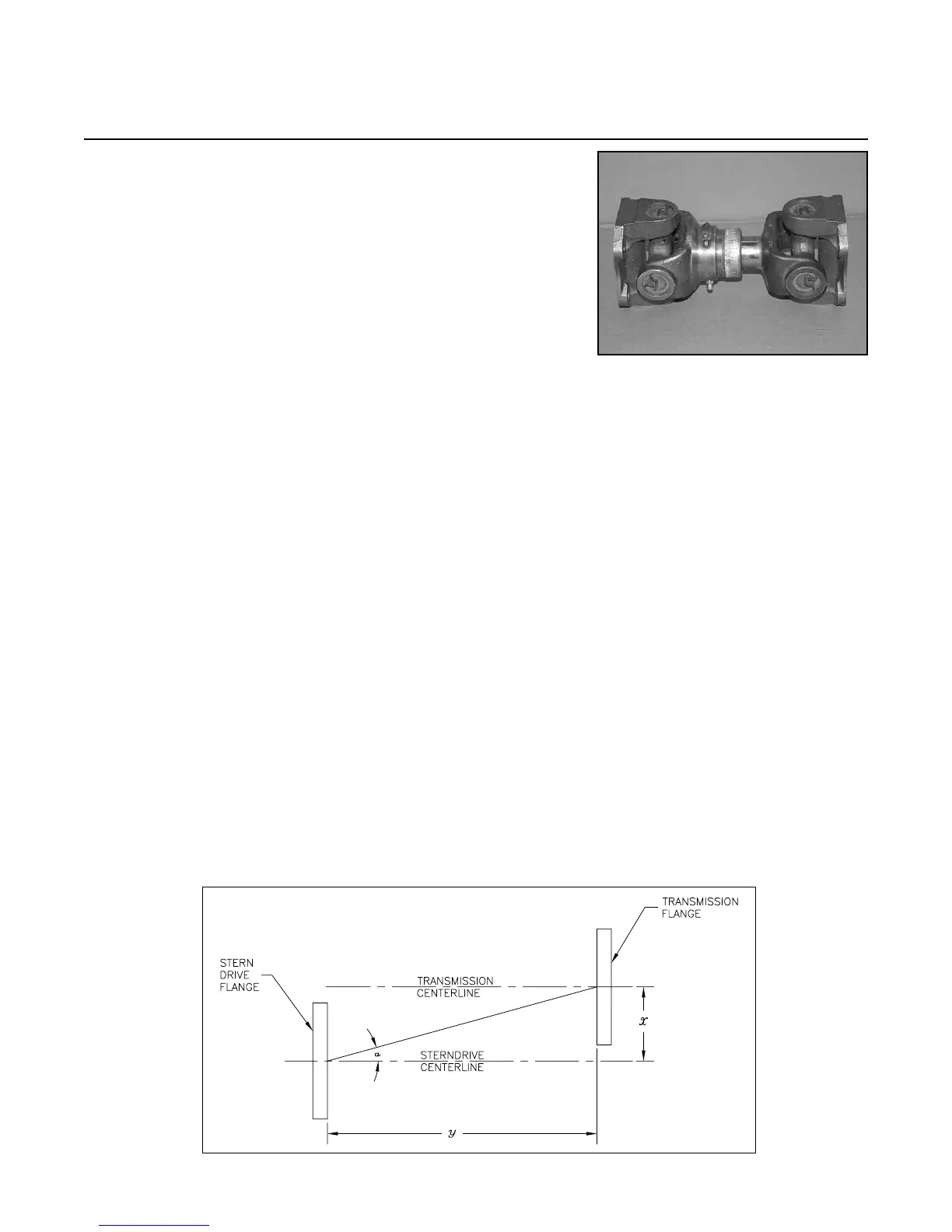
3) To determine vertical offset (see Figure 6D)
(x): x = tan a (y - 3.376 in.) or
(x): x = tan a (y - 8.575 cm)
4) Fix magnetic base, arm and dial indicator
assembly (GO-017) to transmission output
ange.
5) Rotate transmission ange indicating the face
of the alignment ange. All facial mea-
surements must be within .010 in. (.25 mm).
6) Rotate transmission ange indicating the cir-
cumference of the alignment ange. All mea-
surements must be within .010 in. (.25 mm).
Offset measurements are according to calcula-
tion in section D3 above.
7) Refer to Step 16 on pages 68 - 69 in this manual
for u-joint extension shaft installation.
FIGURE 6C
FIGURE 6D