500 SERIES INSTALLATION MANUAL JULY 2016PAGE 30
Step 6: Alignment Procedures (continued)
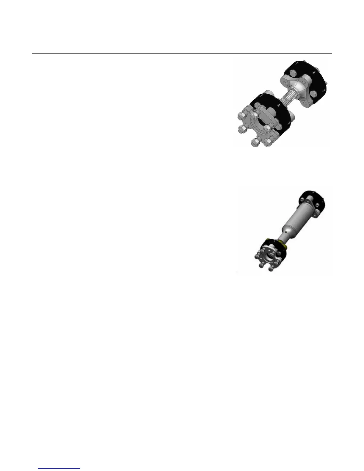
C) Rubber Coupling Extension Shafts
1) Remove frost plug (10-485).
2) Fasten alignment ange (11-284) to gimbal
carrier.
3) Fix magnetic base, arm and dial indicator
assembly (GO-017) to transmission output
ange. Complete assembly must be rigidly
fastened.
4) Rotate transmission ange indicating the
face of the alignment ange. All facial
measurements must be within .010 in. (.25 mm).
5) Rotate transmission ange indicating the
circumference of the alignment ange. All
measurements must be within .010 in. (.25 mm).
6) Remove alignment ange and install frost plug.
7) Install rubber coupling drive shaft assembly
according to Step 15 on pages 64 - 67 in this
manual.
8) For longer extension shafts, an extension piece
should be attached to the transmission ange.
The dial indicator base can be xed to this
extension piece allowing the indicator to reach
the alignment ange. The extension piece, dial
indicator base and arm must all be rigidly
fastened.
Part # 30-264
Part # 30-272
NOTE: Drawing shows drive
in counterclockwise position
NOTE: Drawing shows drive
in clockwise position