NOTE: Verify correct shaft length before proceeding.
NOTE: Apply Loctite to all fasteners in this step before
fastening occurs.
NOTE: Rotation determined by viewing transmission
ange from stern of vessel.
“CCWR” = Counterclockwise rotation
“CWR” = Clockwise rotation.
15.1 Install the adapter ange (11-187) onto the back of the
transmission using:
• Six (6) M-16 H.H.C.S (11-192)
• Six (6) M-16 Belleville Washers (11-193)
• Six (6) M-16 Nuts (11-194)
15.2 Prior to assembly, place three (3) H.H.C.S. (10-486)
and three (3) Belleville washers (11-191) into the rubber
coupling (10-484) element according to the clockwise and
counterclockwise rotations. These fasteners will attach to
the center drive shaft component (11-266 & 11-308). Install
the rubber coupling (10-484) to the adapter ange (11-187)
using:
30-264 Assembly
• Three (3) M-14 H.H.C.S. (10-486)
• Three (3) Belleville Washers (11-191)
30-272 Assembly
• Three (3) M-14 S.H.C.S. (11-190)
• Three (3) Belleville Washers (11-191)
Counterclockwise rotation: The fasteners (10-486 or 11-
190) should be inserted through the rubber coupling in the
direction of the arrows. When attaching the rubber coupling
to the adapter ange (11-187), point arrows on the rubber
coupling toward the adapter ange (11-187).
IMPORTANT: Thick section of rubber element should
ALWAYS be in compression between driving and driven
bolts.
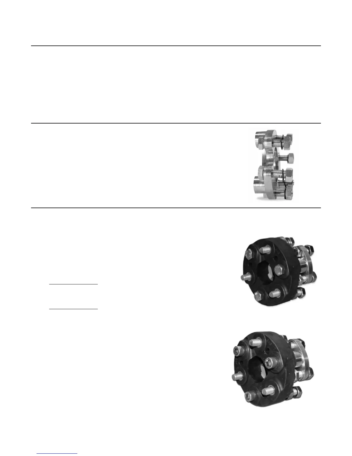
Step 15: Rubber Coupling Extension Shaft(s) Installation
30-272
CCWR
30-264
CCWR
500 SERIES INSTALLATION MANUAL JANUARY 2010PAGE 64