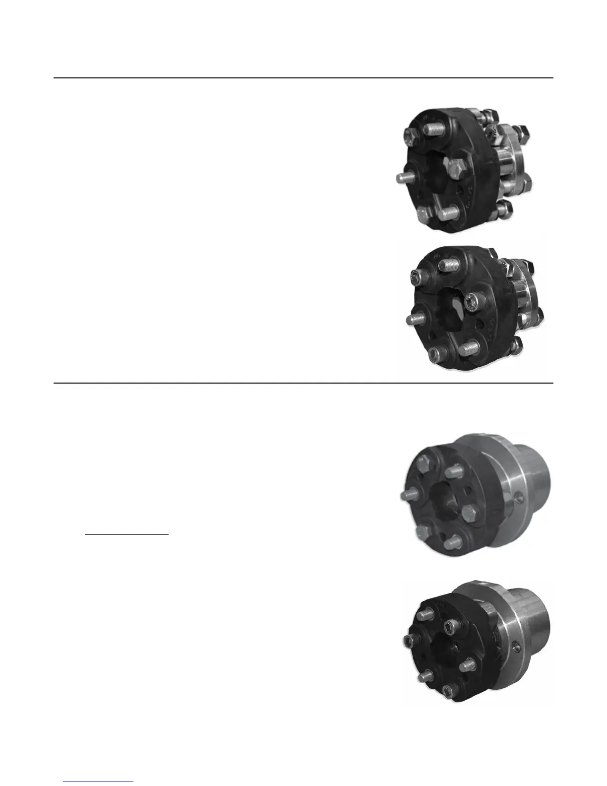
Clockwise rotation: The fasteners (10-486 or 11-190)
should be inserted through the rubber coupling against
the direction of the arrows. When attaching the rubber
coupling to the adapter ange (11-187), point arrows on
the rubber coupling away from the adapter ange (11-
187).
IMPORTANT: Thick section of rubber element should
ALWAYS be in compression between driving and driven
bolts.
15.3 Prior to assembly, place three (3) H.H.C.S. (10-486)
and three (3) Belleville washers (11-191) into the rubber
coupling (10-484) element. These fasteners will attach to
the center drive shaft component (11-266; 20-028). Attach
the second rubber coupling (10-484) to the gimbal carrier
ange (10-466) using:
30-264 Assembly
• Three (3) M-14 H.H.C.S. (10-486)
• Three (3) Belleville Washers (11-191)
30-272 Assembly
• Three (3) M-14 S.H.C.S. (11-190)
• Three (3) Belleville Washers (11-191)
Counterclockwise rotation: The fasteners (10-486 or 11-
190) should be inserted through the rubber coupling in
the direction of the arrows. When attaching the rubber
coupling to the gimbal carrier ange (10-466), point
arrows on the rubber coupling toward the gimbal carrier
ange (10-466).
IMPORTANT: Thick section of rubber element should
ALWAYS be in compression between driving and driven
bolts.
Step 15: Rubber Coupling Shaft(s) Installation (continued)
30-272
CWR
30-264
CWR
30-272
CCWR
30-264
CCWR
500 SERIES INSTALLATION MANUALJANUARY 2010 PAGE 65