500 SERIES INSTALLATION MANUAL JULY 2016PAGE 66
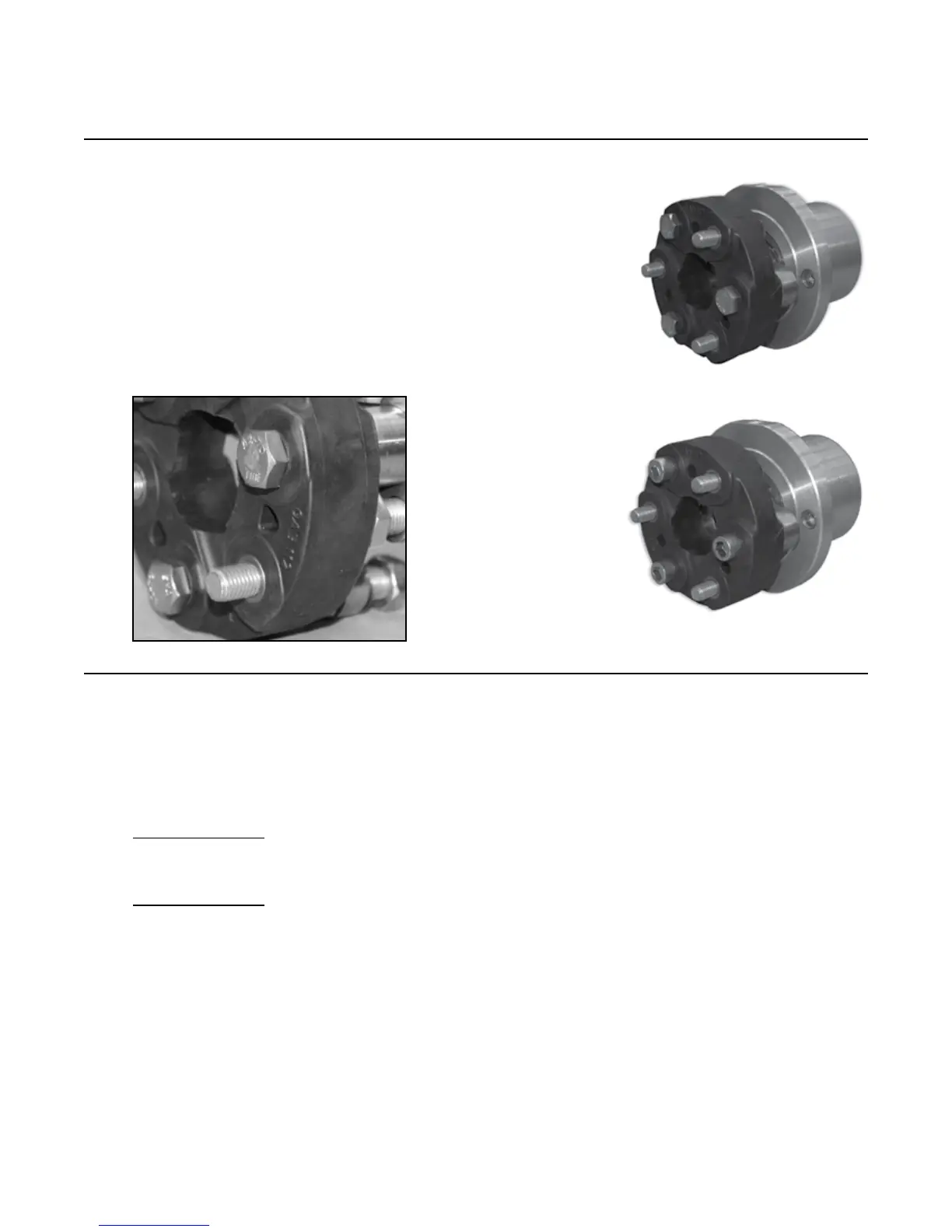
Clockwise rotation: The fasteners (10-486 or 11-190)
should be inserted through the rubber coupling against
the direction of the arrows. When attaching the rubber
coupling to the gimbal carrier ange (10-466), point
arrows on the rubber coupling
away from the gimbal carrier ange (10-466).
IMPORTANT: Thick section of rubber element should
ALWAYS be in compression between driving and driven
bolts.
15.4 Insert the center drive shaft component (see below) in
between the two (2) rubber couplings (10-484) using:
• Six (6) M-14 H.H.C.S. (10-486)
• Six (6) Belleville Washers (11-191)
30-264 Assembly
• Adapter (11-266)
• Drive Shaft (11-267)
30-272 Assembly
• Adapter (11-308)
• Drive Shaft (20-028)
Tighten all fasteners to 70 lb. ft. (95 Nm).
30-272
CWR
30-264
CWR
Step 15: Rubber Coupling Shaft(s) Installation (continued)