500 SERIES INSTALLATION MANUALJULY 2016 PAGE 13
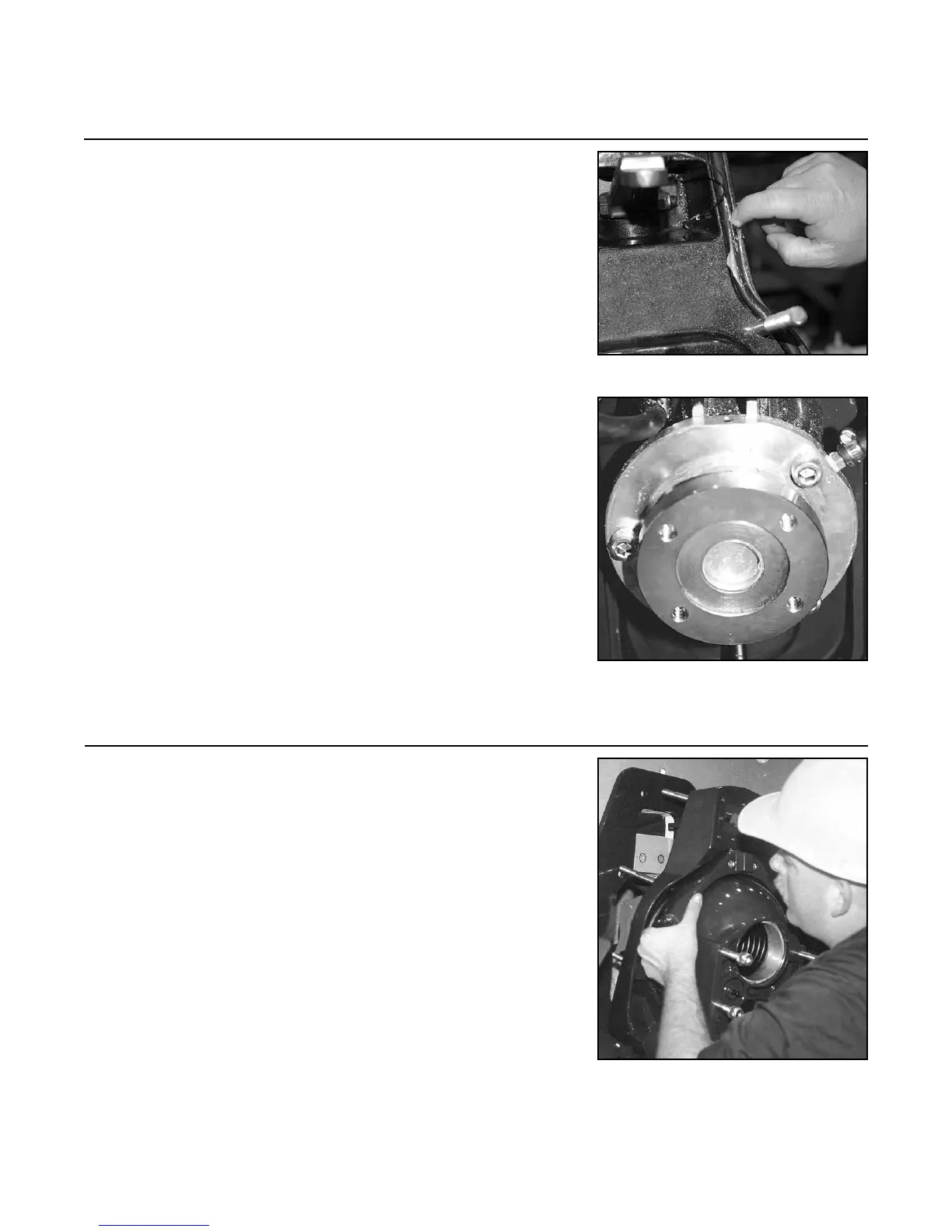
2.1 Grease the transom assembly gasket with marine grade
grease (see Figure 2A).
NOTE: If the gimbal carrier assembly is not mounted
in the gimbal housing bore, it should be done at this time
(see Figure 2B).
NOTE: The gimbal carrier ange may differ from the
one pictured in Figure 2B per application.
1) Lightly grease the carrier assembly and o-ring,
then slide it into the gimbal housing bore.
2) Rotate the carrier assembly to achieve correct
orientation. The brass nipple should be at
approximately two o’clock.
3)
Torque the three (3) fasteners to 70 lb. ft. (95 Nm).
NOTE: The gimbal carrier ange may differ from the
one pictured in Figure 2B per application.
2.2 Guide the transom assembly studs through the eight (8)
holes in the transom.
NOTE: The weight of the transom assembly is 81 lbs.
(36.7 kg). Use caution when lifting.
NOTE: Some installations/applications require an ex-
ternal adapter plate.
NOTE: Proper stud length varies due to hull thickness.
Stud length is also dictated by peripheral equipment that
mounts inside the hull (steering cylinder bracket, inner
transom plate, drive shaft shroud, etc.). Verify correct
stud length before continuing past this step.
Step 2: Transom Assembly Installation
FIGURE 2B
FIGURE 2C
FIGURE 2A