6. - Putting into service
GMD240 - 280 - 310
43
KN204BGB_G
Disc mower
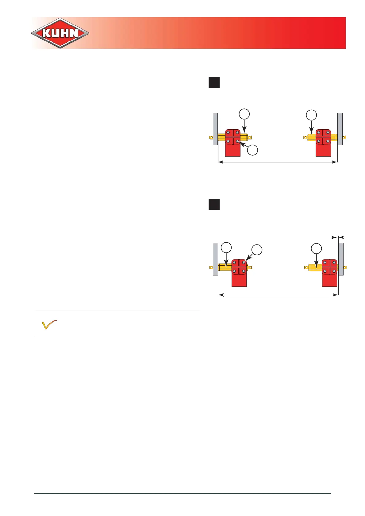
If measure A is comprised between 2.10 mm
(6’11") ad 2.25 mm (7’04"):
- Place lower links in position b.
Adjust the hitch pins:
- Loosen the 8 screws (3).
- Centre hitch pin (1) with regards to the mounting
plate.
- Tighten 4 hitch pin screws (1):
• Torque value: 12.3 daNm (91 lbf ft).
- Position hitch pin (2) at a distance of X = 825 mm
(2’8").
- Tighten 4 hitch pin screws (2):
• Torque value: 12.3 daNm (91 lbf ft).
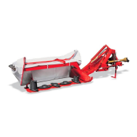
If measure A is comprised between 2.25 mm
(7’04") ad 2.40 mm (7’10"):
- Place lower links in position c.
Adjust the hitch pins:
- Loosen the 8 screws (3).
- Position hitch pin (2) at a distance of G = 10 mm
((0.4"))
- Tighten 4 hitch pin screws (1):
• Torque value: 12.3 daNm (91 lbf ft).
- Position hitch pin (2) at a distance of X = 825 mm
(2’8").
- Tighten 4 hitch pin screws (2):
• Torque value: 12.3 daNm (91 lbf ft).
It is possible to adjust the coupling more
precisely by adjusting the lower links sideways.
1
2
3
B
A