4-30
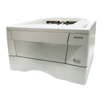
FS-1900
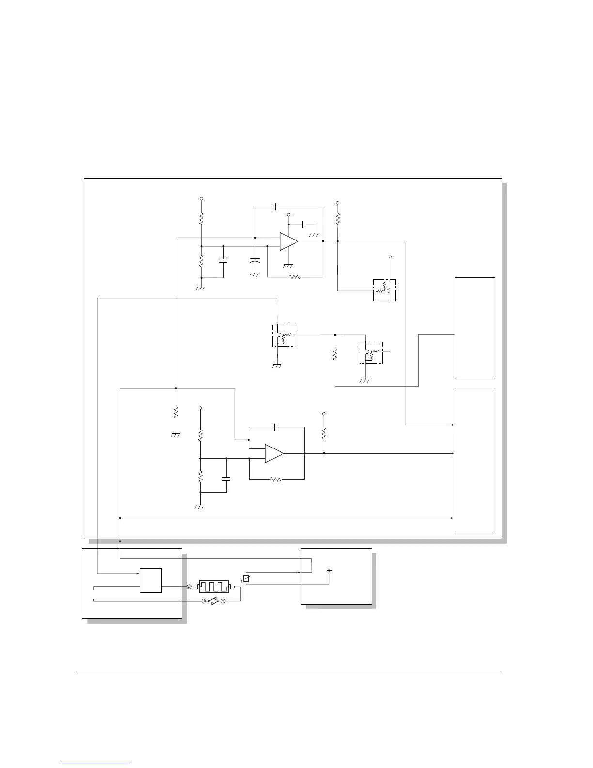
Heater lamp control circuit
The heater lamp control circuit turns the heater lamp on and off which is located coaxially inside
the heat roller. The surface of the roller maintains the constant temperature needed to permanently
fuse the toner on paper.
The heater lamp is directly fed with AC primary power (220 - 240 V or 120 V) which is supplied
from the power supply unit.
Figure 4-3-9 heater lamp control circuit
+
THERM
HEATON*
THERM
THDEAD
R219
R217
+5V1
+5V1
+5V1
+5V1
+5V1
+5V1
+5V1
8
7
4
5
6
HTEMP*
U205-2
U205-1
R233
1M
Q204
3
3
2
2
1
1
393
393
R228
4
5
3
6
1
2
HEATON
QA201B
QA201A
+
−
+
−
Engine
gate
array
(U204)
CPU
(U201)
TRC
PC
AC
Engine board
Heater lamp
Thermal cutout
Thermisor
Fuser board
Power supply unit
1.3k
54
3
63
4
P34/RT04
/HRQ
P43/PPG3
P50/AN0
HEATON

 Loading...